All fiber based short pulse amplification at one micron

a modelocked fiber laser and all fiber technology, applied in the field of all fiber based short pulse amplification at one micron, can solve the problems of difficult to achieve the practical application of ultra-short pulse and high power lasers, and the distortion of pulse shapes, and the practical usefulness of ultra-short high power lasers is often hindered

Active Publication Date: 2006-10-12
POLARONYX
View PDF7 Cites 39 Cited by
  • Summary
  • Abstract
  • Description
  • Claims
  • Application Information

AI Technical Summary

Benefits of technology

[0011] It is another aspect of the present invention to provide a method of using nonlinear polarization evolution (NPE) and dispersion managed fiber cavity to manipulate the pulse propagation in the cavity and balance the self phase modulation (SPM) and dispersion induced pulse broadening / compressing. This method of polarization pulse shaping generates transform-limited pulse shapes through combinational effects of fiber length, the non-linear effects and dispersion such that the above-described difficulties encountered in the prior art can be resolved.

Problems solved by technology

Conventional technologies of generating short pulse mode-locked fiber laser are still confronted with technical difficulties and limitations that the amplify the short pulse, e.g., a ps to 100 fs pulse, to a high energy level, e.g., up to mJ level.
Furthermore, practical applications of the ultra-short pulse and high power laser cannot be easily achieved.
Specifically, the practical usefulness of the ultra-short high power lasers are often hindered by the pulse shapes distortions.
Furthermore, such laser systems are often bulky, difficult for maintaining optical alignment, and also lack sufficient robustness.
All these difficulties prevent practical applications of the ultra-short high power lasers.
Historically, generation of mode-locked laser with the pulse width down to a femtosecond level is a difficult task due to limited resources of saturation absorbers and anomalous dispersions of fibers.
Conventionally, short pulse mode locked fiber lasers operated at wavelengths below 1.3 μm present a particular challenge is that there is no simple all fiber based solution for dispersion compensation in this wavelength regime.
Unfortunately these devices require the coupling of the fiber into a bulk device, which results in a laser that is highly sensitive to alignment and thus the environment Several conventional techniques disclosed different semiconductor saturation absorbers to configure the ultra-short high power laser systems.
However, such configurations often developed into bulky and less robust systems due to the implementations of free space optics.
The limitations for practical application of such laser systems are even more pronounced due the pulse shape distortions when the pulse width is further reduced compounded with the requirement of high power fiber amplification.
When the pulse width narrows down to femtosecond level and the peak power increases to over 10 kW, strong nonlinear effects such as self phase modulation (SPM) and XPM will cause more serious spectral and temporal broadening.
These nonlinear effects and spectral and temporal broadening further causes a greater degree of distortions to the laser pulses.
The technical difficulties cannot be easily resolved even though a large mode area (LMA) fiber can be used to reduce SBS and SRS to increase saturation power.
However, the large mode area fiber when implemented will in turn cause a suppression of the peak power and leads to an undesirable results due to the reduction of the efficiency
For these reasons, the conventional technologies do not provide an effective system configuration and method to provide effective ultra-short pulse high power laser systems for generating high power laser pulses with acceptable pulse shapes.
In addition to the above described difficulties, these laser systems require grating pairs for dispersion control in the laser cavity.
Maintenance of alignment in such systems becomes a time consuming task thus prohibiting a system implemented with free space optics and grating pairs from practical applications.
Also, the grating pairs further add to the size and weight of the laser devices and hinder the effort to miniaturize the devices implemented with such laser sources.

Method used


Image

  • All fiber based short pulse amplification at one micron
  • All fiber based short pulse amplification at one micron
  • All fiber based short pulse amplification at one micron

Examples


Embodiment Construction

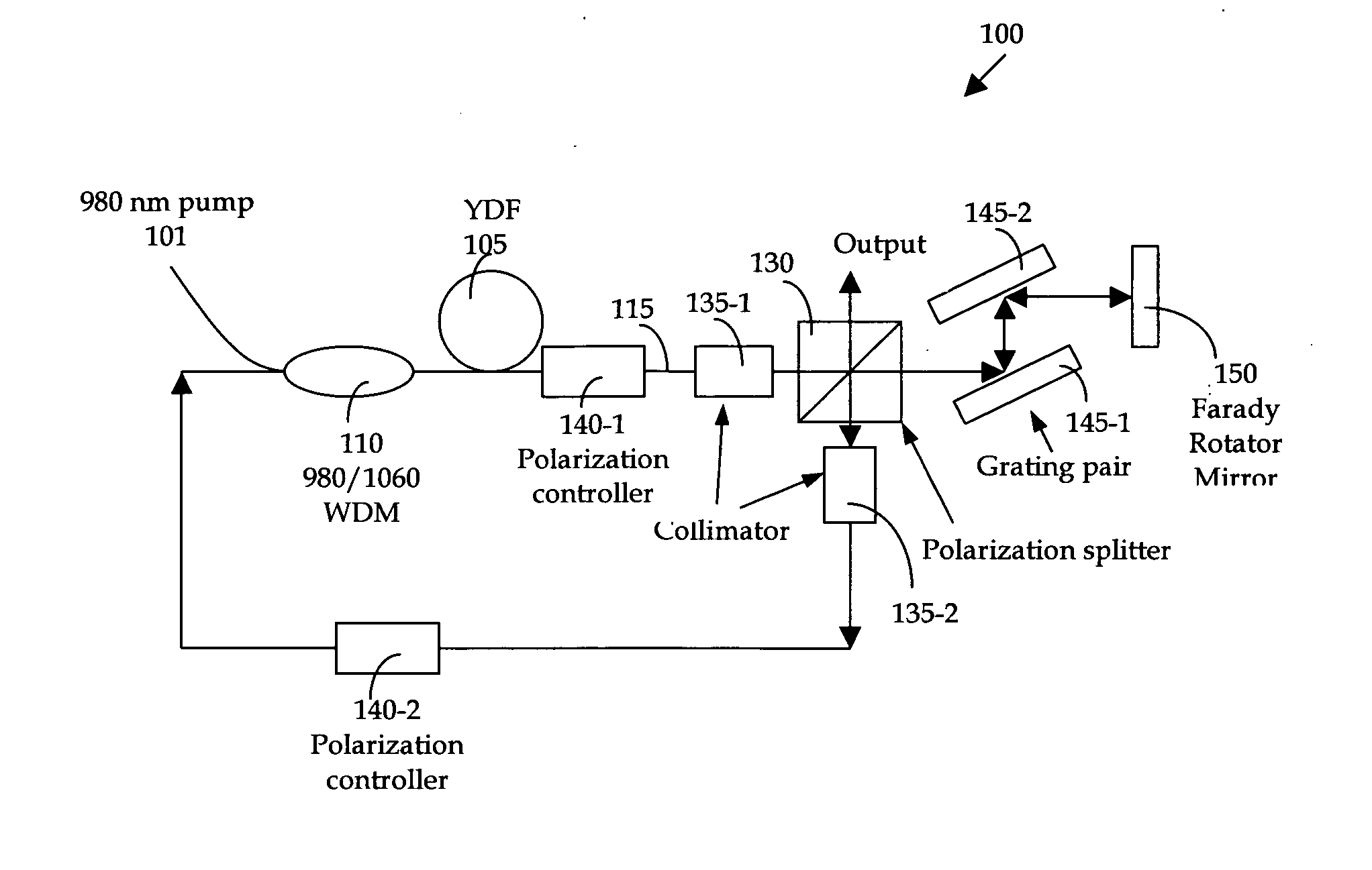
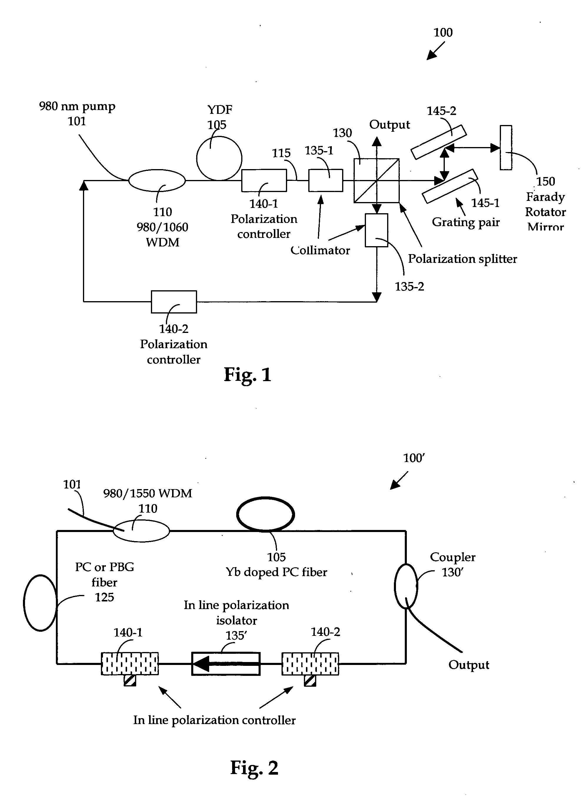
[0025] Referring to FIG. 1 for a schematic diagram of a nonlinear polarization pulse-shaping mode locked fiber laser 100 of this invention. The fiber laser is a ring structure laser that includes a gain medium Ytterbium (Yb) doped fiber (YDF) 105, a fist and a second collimator 135-1 and 135-2 respectively, a first and second polarization controllers 140-1 and 140-2 respectively, a 980 / 1550 WDM coupler 110, and an output beam splitter 130. The output beam splitter 130 is coupled to a pair of gratings 145-1 and 145-2 coupled to a Faraday rotator mirror 150. A half-meter of YDF 105 is used in the fiber laser as a gain medium and is used to amplify and compress the pulse width. The fiber has a high doping concentration, e.g., 600 dB / m at 976 nm, with a dispersion of −55 ps / nm / km. A 980 nm high power pump laser diode 101 coupled through a wavelength division multiplexer 110 is used to pump the YDF 105 to amplify the pulses circulating in the cavity. The rest of the cavity comprising a s...


PUM


Abstract

A fiber laser cavity that includes a laser gain medium for receiving an optical input projection from a laser pump. The fiber laser cavity further includes a positive dispersion fiber segment and a negative dispersion fiber segment for generating a net negative dispersion for balancing a self-phase modulation (SPM) and a dispersion induced pulse broadening/compression in the fiber laser cavity for generating an output laser with a transform-limited pulse shape wherein the wherein said laser gain medium further comprising a double cladding Ytterbium-doped Photonics crystal fiber (DC YDPCF) for amplifying and compacting a laser pulse. The fiber laser cavity further includes a polarization sensitive isolator and a polarization controller for further shaping the output laser.

Description

[0001] This Formal Application claims a Priority Date of Apr. 6, 2005 benefit from a Provisional Patent Application 60 / 669,187 filed by the same Applicant of this Application. Furthermore, this Formal application is a Continuation in Part (CIP) Application of another patent application Ser. No. 11 / 136,040 filed on May 23, 2005 by the same Applicant of this Application. The disclosures made in 60 / 669,187 and Ser. No. 11 / 136,040 are hereby incorporated by reference in this patent application.FIELD OF THE INVENTION [0002] The present invention relates generally to apparatuses and methods for providing short-pulsed mode-locked fiber laser. More particularly, this invention relates to new configurations and methods for providing a nonlinear polarization pulse-shaping mode-locked fiber laser with improved and better controllable pulse shapes. BACKGROUND OF THE INVENTION [0003] Conventional technologies of generating short pulse mode-locked fiber laser are still confronted with technical d...

Claims


Application Information

Patent Timeline
Patent Type & Authority Applications(United States)
IPC IPC(8): H01S3/30
CPCG02B6/02247G02B6/02357H01S3/0057H01S3/0064H01S3/06708H01S3/06712H01S3/1618H01S3/06741H01S3/06791H01S3/08004H01S3/094007H01S3/1112H01S3/06725
Inventor LIU, JIAN
Owner POLARONYX
Why Eureka
Try Eureka