Multi-thread processor and method for operating such a processor

a multi-thread processor and processor technology, applied in the field of multi-thread processors, can solve the problems of large space and high implementation costs, and achieve the effects of saving space, simplifying the driving of the processor, and simplifying the driving of the command buffer

Inactive Publication Date: 2006-10-12
INFINEON TECH AG
View PDF10 Cites 4 Cited by
  • Summary
  • Abstract
  • Description
  • Claims
  • Application Information

AI Technical Summary

Benefits of technology

[0019] A further advantage of the present invention is that the acceptance of a potential latency time owing to the waiting for the memory values which are requested by a load command and the associated generation of the context switch-over signal according to the invention permits the command buffers to be arranged clearly above the memory read access unit in the pipeline of the multi-thread processor. In conventional implementations of multi-thread processors, a conflict-free zone of a plurality of pipeline stages, which is conditioned on the basis of other periphery conditions such as, for example, the handling of interrupts or the simplification of the driving of the processor, is embodied above the memory read access unit or load unit. This means that the conflict-free zone of pipeline stages which is inherently present above the memory read access unit owing to the other aforesaid periphery conditions is used according to the invention to arrange the command buffers above this conflict-free zone and to control by means of the context switch-over signal which is generated according to the invention. As a result, compared to the known implementation only very small replay buffers or command buffers are required according to the invention. This saves space on the circuit board of the multi-thread processor. Furthermore, the driving of the command buffers is simplified, thus saving further costs.
[0020] A further particular advantage of the inventive multi-thread processor and of the inventive method is that the data flow, the memory values and the command flow, context identifier and target register identifier are synchronized by means of the synchronization unit according to the invention.
[0021] In a restricted version of the inventive processor, the processor comprises
[0022] a memory system which has a plurality of memory locations, wherein one memory location can be addressed by a memory address and stores a variable memory value, and which makes available the corresponding memory value in response to a request transmitted to the memory system and memory address, and transmits the associated validity signal with a positive logic signal level to the synchronization unit;
[0023] a processor pipeline for processing program commands of various threads, the processor pipeline having at least:
[0024] a memory read access unit which in the case of a load command transmits the load cycle indicator flag with a positive logic signal level to the synchronization unit in order to indicate a load cycle at the memory system, and makes available the context identifier in order to indicate the corresponding context of the load command and the target register identifier in order to indicate the target memory location of the memory system of the load command; and

Problems solved by technology

In a multi-thread architecture this inevitably leads to the implementation of command buffers which are arranged downstream of the memory read access unit.
This means that relatively large command buffers have to be provided and they require a large amount of space and their implementation entails high costs.

Method used


Image

  • Multi-thread processor and method for operating such a processor
  • Multi-thread processor and method for operating such a processor
  • Multi-thread processor and method for operating such a processor

Examples


Embodiment Construction

[0043] Identical or functionally identical elements and signals have been provided with the same reference symbols in the figures, unless stated otherwise.

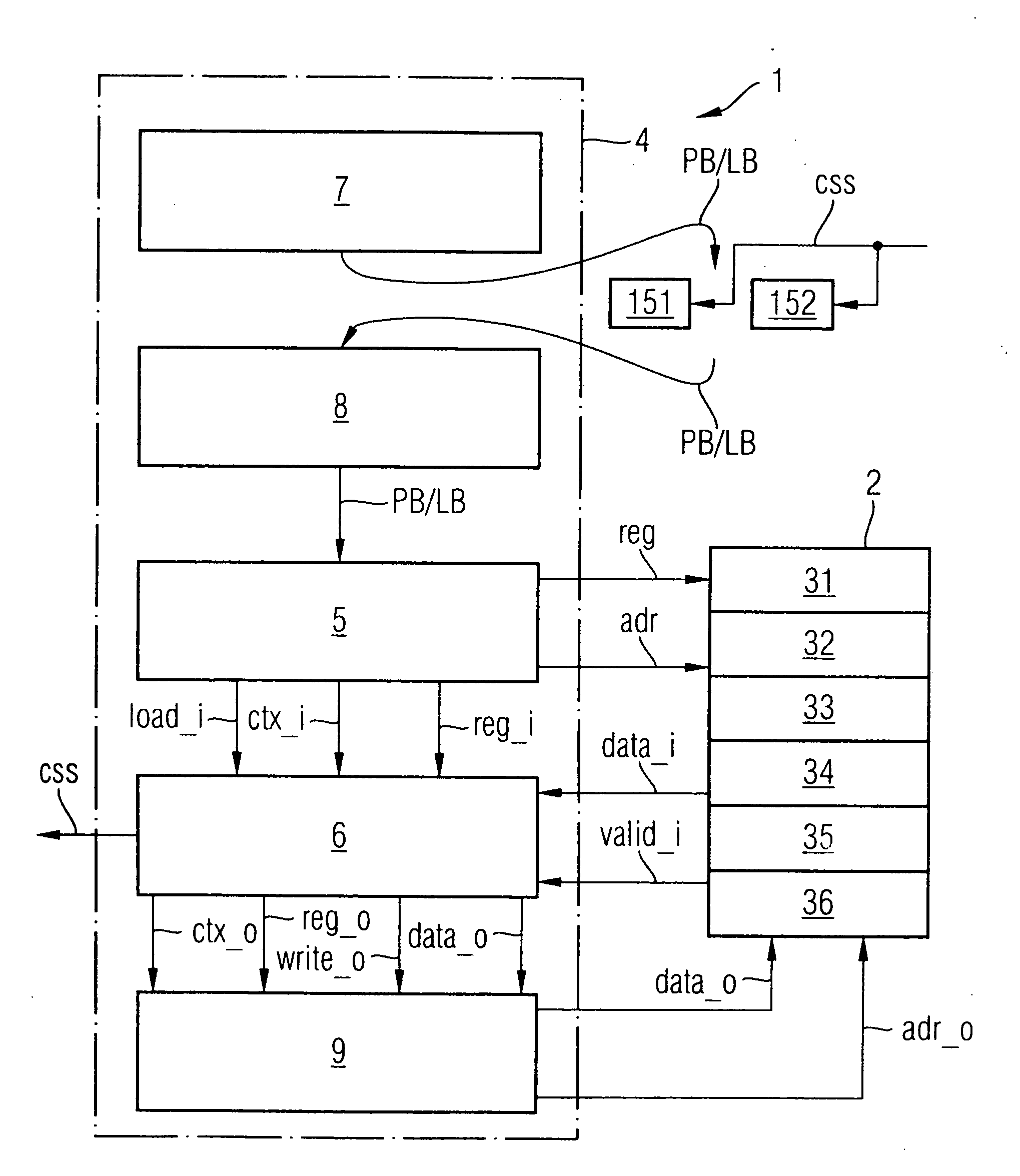
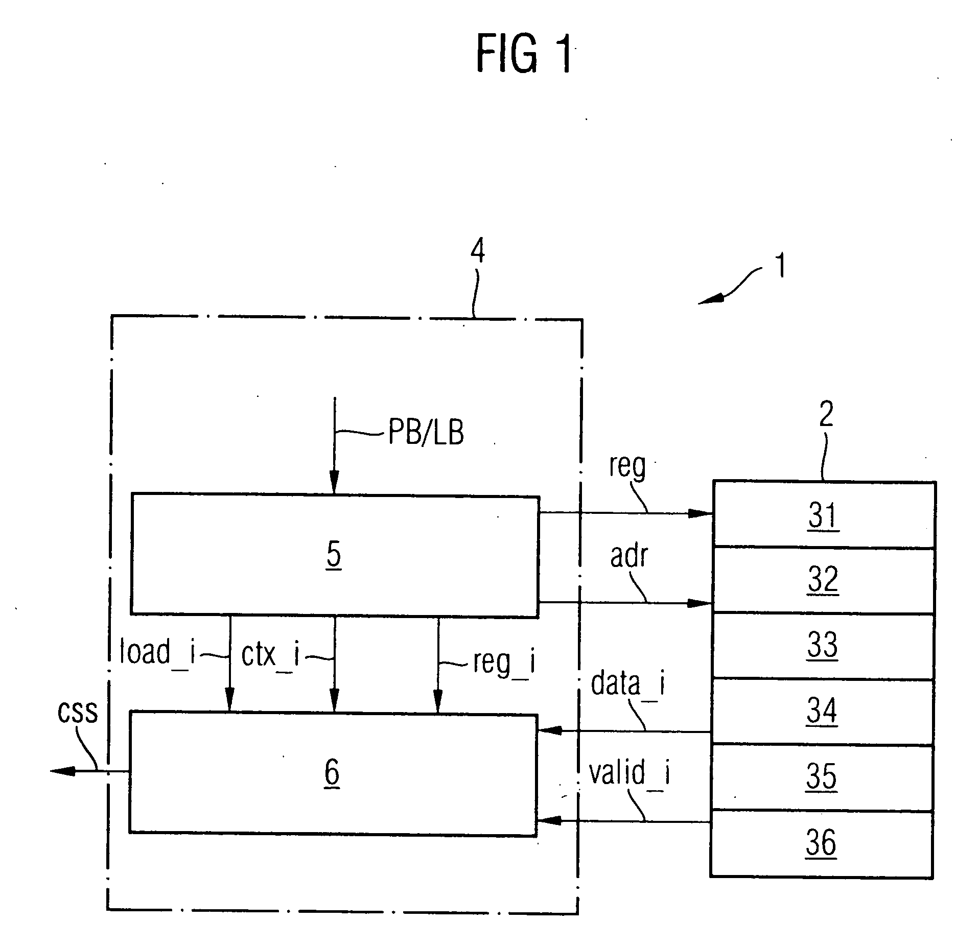
[0044]FIG. 1 shows a schematic block circuit diagram of a first preferred exemplary embodiment of the multi-thread processor 1 according to the invention. The multi-thread processor 1 according to the invention has a memory system 2 which is composed of a plurality of memory locations 31-36. A memory location 31-36 can be addressed by means of a memory address adr, and stores memory values data_i. The memory system 2 provides the corresponding memory value data_i of the corresponding memory location 31-36 in response to a request req transmitted to the memory system 2, and the memory address adr. The memory system 2 also provides an associated validity signal valid_i for specifying the validity of the supplied memory value data_i to the synchronization unit 6 or transmits it to the synchronization unit 6. The validity signal vali...


PUM


Abstract

A multithread processor with synchronization of a command flow, with an associated data flow and with generation of a memory-triggered context switch signal comprises a synchronization device configured, when receiving a load cycle indicator flag with a positive logic signal level from a memory read access unit, to load and buffer in a synchronized fashion an associated context identifier and a target register identifier and to forward the context identifier and the target register identifier to a downstream pipeline stage and, when receiving a validity signal with a positive logic signal level from a memory system, to load and buffer in a synchronized fashion an associated memory value, and to forward the memory value to the pipeline stage. The processor comprises further a logic circuit generating, when the load cycle indicator flag with a positive logic signal level and the validity signal are received, a context switch signal with a negative logic signal level.

Description

BACKGROUND OF THE INVENTION [0001] 1. Field of the Invention [0002] The invention relates to a multi-thread processor having a synchronization unit for synchronizing a command flow with an associated data flow, and for generating a memory-triggered context switch-over signal, and a method for operating such a processor. [0003] 2. Description of the Prior Art [0004] Embedded processors and their architectures are measured by their power consumption, their throughput rate, their utilization rate, their costs and their real time capability. The principle of multi-threading is used in particular to increase the throughput rate and utility rate. The basic idea of multi-threading is based on the fact that a processor processes a plurality of threads. In this context, use is made in particular of the fact that during a latency time of the one thread it is possible to process program commands of the other thread. In this context, one thread designates a control path of a code or source code...

Claims


Application Information

Patent Timeline
Patent Type & Authority Applications(United States)
IPC IPC(8): G06F9/44
CPCG06F9/3851
Inventor DI GREGORIO, LORENZO
Owner INFINEON TECH AG
Why Eureka
Try Eureka