Method of operating furnace to reduce emissions

a technology of emission reduction and furnace, applied in the field of combustion, can solve the problems of significant combustion taking place in the upper furnace, insufficient residence time for combustion, and difficulty in reducing so as to reduce the stoichiometric ratio of the second group, increase the stoichiometric ratio, and reduce the nox content and co content

Inactive Publication Date: 2006-10-19
PRAXAIR TECH INC
View PDF7 Cites 5 Cited by
  • Summary
  • Abstract
  • Description
  • Claims
  • Application Information

AI Technical Summary

Benefits of technology

[0014] (C) decreasing the NOx content and the CO content of said flue gas by increasing the stoichiometric ratio of said first group of burners and decreasing the stoichiometric ratio of said second group of burners,

Problems solved by technology

Although effective, this arrangement can be problematic for some boilers.
Under these conditions there is not enough residence time available to completely combust the CO formed in the fuel rich stage.
When coupled with a high heat release rate, defined as the heat release per unit furnace volume in the burner zone, this can also lead to significant amounts of combustion taking place in the upper furnace.
This combustion in the upper furnace, in turn, can cause problems with the steam temperature control and can cause additional NOx formation—in some cases actually negating any benefit of staging in the burner zone.
However, although increasing the air preheat temperature would lead to lower emissions under fuel rich conditions it could actually exacerbate some of the problems discussed above with staging in constrained units, particularly steam temperature problems.

Method used


Image

  • Method of operating furnace to reduce emissions
  • Method of operating furnace to reduce emissions
  • Method of operating furnace to reduce emissions

Examples


Embodiment Construction

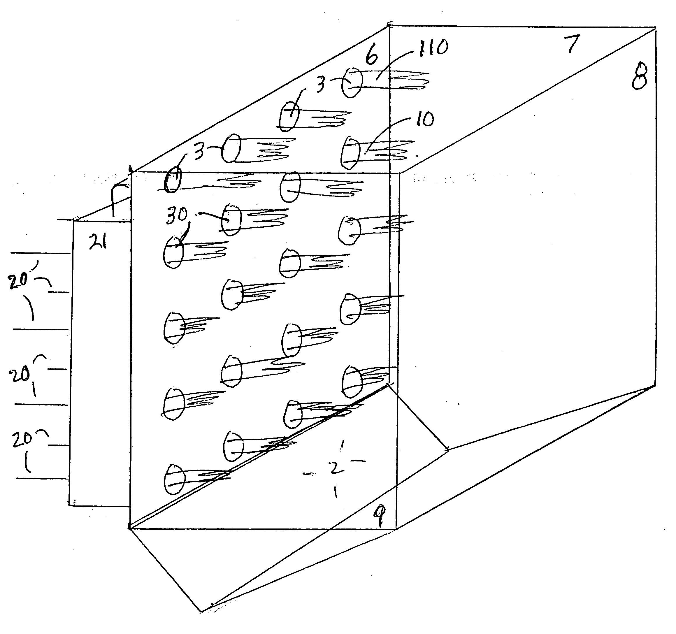
[0029]FIG. 3A shows combustion device 1, which can be any apparatus wherein combustion is carried out in the interior 2 of the device. Preferred combustion devices include furnaces and boilers which are used to generate steam by conventional means, not shown.

[0030] The furnace in FIG. 3A is depicted with four rows of burners 30 arranged in four burners per row. For reference purposes, these burners are identified as shown in FIG. 3B by a letter and a number, with the letter identifying the row (A being the row highest in elevation and D being the row lowest in elevation) and the number identifying the columnar position in left-to-right ascending sequence.

[0031] The invention can be practiced as well with furnaces containing more or fewer than the 16 burners depicted in FIGS. 3A and 3B, and with more or fewer rows and more or fewer columns of burners. Also, the burners can be arrayed in a staggered or offset fashion so that the burners in adjacent rows lie on a diagonal line instea...


PUM


Abstract

Emissions of NOx and CO are reduced from combustion devices such as coal-fired furnaces by increasing the stoichiometric ratio of burner(s) having a lower average temperature and increasing the stoichiometric ratio of burner(s) having a higher average temperature.

Description

[0001] This application claims priority from prior copending U.S. provisional application Ser. No. 60 / 644,889, filed Jan. 18, 2005.FIELD OF THE INVENTION [0002] The present invention relates to combustion in, for instance, a coal-fueled boiler for generating electric power. BACKGROUND OF THE INVENTION [0003] Nitrogen oxides, typically called “NOx”, have been implicated in the formation of ground level ozone and acid rain. Combustion of pulverized coal, or other nitrogen bearing hydrocarbonaceous fuels, in boilers represents a significant source of NOx emissions. Current and pending regulations require that NOx emissions from these facilities be reduced significantly from present values. [0004] One technology that is currently used to reduce NOx emissions is air staging in the furnace. In this technology the airflow to the burners, which may be low NOx burners, is typically less than that required to completely combust the fuel. This arrangement creates a fuel-rich zone that tends to...

Claims


Application Information

Patent Timeline
Patent Type & Authority Applications(United States)
IPC IPC(8): F23B99/00F23B90/00
CPCF23C6/045F23C2201/101F23C2201/20Y02E20/344F23J2215/10F23L7/007F23C2900/99004Y02E20/34
Inventor KACZENSKI, EDWARDBOOL, LAWRENCE E. IIIKOBAYASHI, HISASHI
Owner PRAXAIR TECH INC
Why Eureka
Try Eureka