Cylindrical AC/DC Magnetron with Compliant Drive System and Improved Electrical and Thermal Isolation

a technology of ac/dc magnetron and a drive system, which is applied in the direction of electrolysis components, vacuum evaporation coatings, coatings, etc., can solve the problems of constant change of tube shape, complex problems in effectively transferring electrical power to a rotating target tube, and difficult to take into account. , to achieve the effect of effective initial vacuum sealing engagement, control and minimize the effects of heat generation

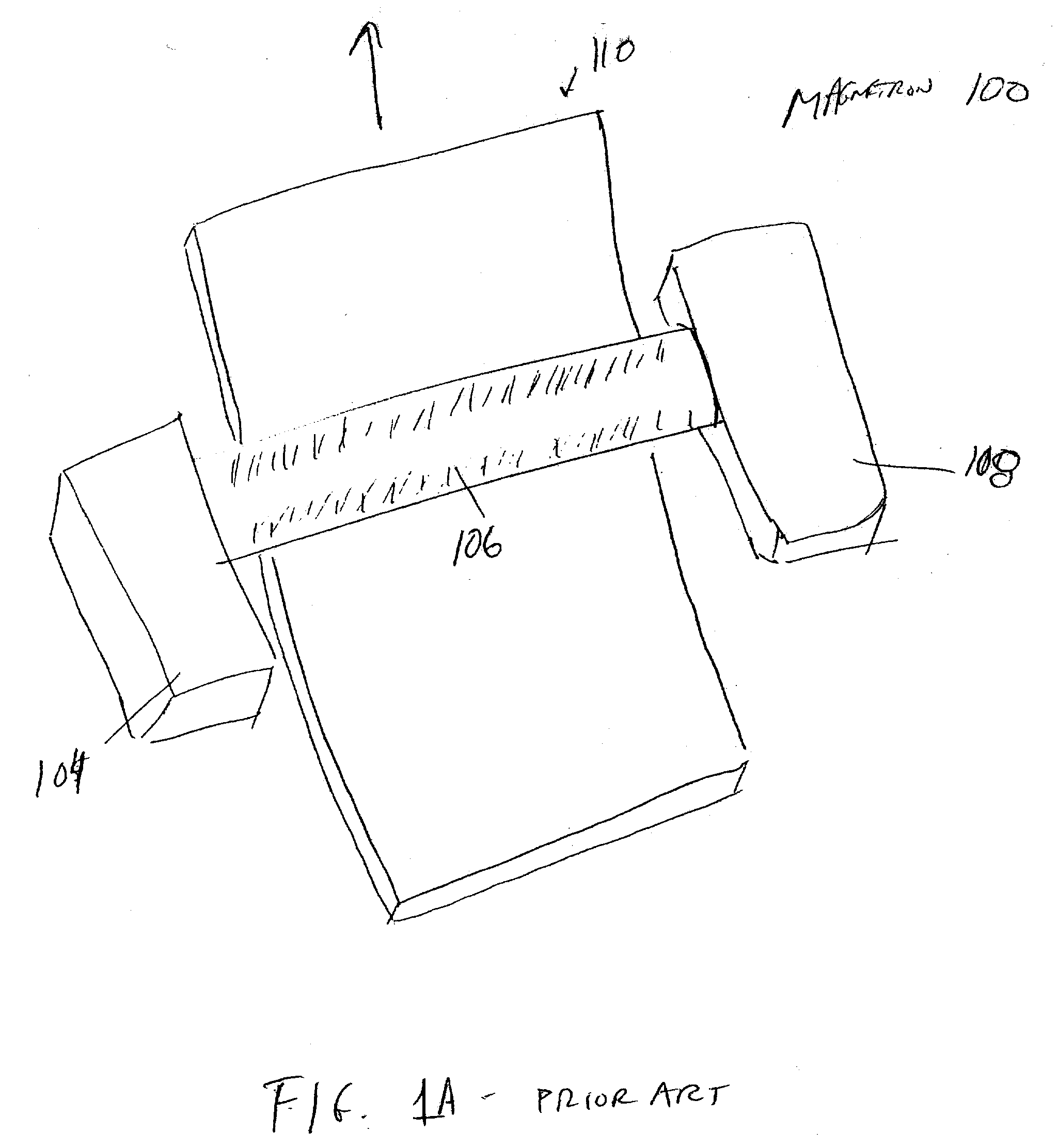
Inactive Publication Date: 2006-10-19
VON ARDENNE ANLAGENTECHNIK GMBH
View PDF4 Cites 4 Cited by
  • Summary
  • Abstract
  • Description
  • Claims
  • Application Information

AI Technical Summary

Benefits of technology

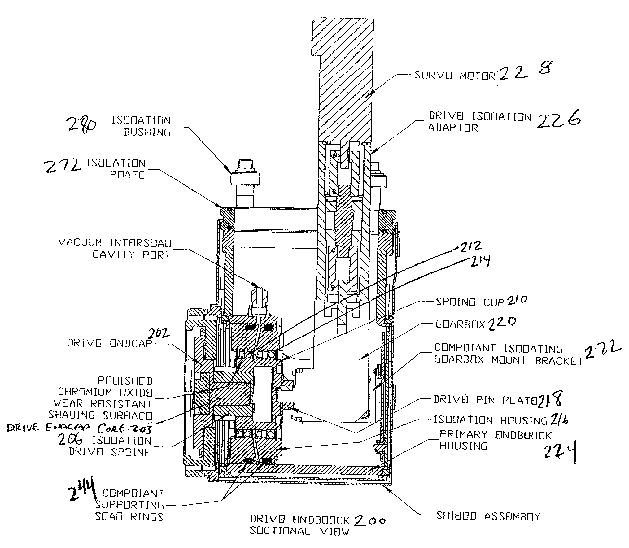
[0013] The present invention adapts to a greater amount of target tube manufacturing and process related variations with angularly compliant mechanisms at each end. The mechanisms also accommodate growth or variations in length of the target tube along the axis. This compliance reduces the transmission of stress within the structure of the magnetron and allows for more consistent and reliable operation.
[0015] Electrical isolation is another aspect of the invention. Redundant isolation areas are included to prevent grounding of the device and maintain the floating electrical isolation during operation both initially and over extended periods of usage without maintenance.
[0016] Another aspect of the invention are thermal systems to control and minimize the effects of heat generated at static locations where electrical power is provided to the device and at dynamic locations where electrical power is transferred within the device to rotating components. Control and minimization of AC inductive heating is achieved by material selection, construction and geometry taking into account constraints of the sputter deposition process.
[0017] Another aspect of the invention incorporates dual water and vacuum sealing to handle the dynamic flow of water through a rotating target in vacuum conditions. The dynamic water seals operate in a primary / secondary set with an unobstructed draining of the interseal area which provides a conditional alarm function while precluding the pressurization of the secondary seal, thereby increasing its operational reliability. The dynamic vacuum seals operate in a primary / secondary set with a differentially pumped interseal area between the primary and secondary seals to provide an effective initial vacuum seal engagement while also providing a backup seal and monitoring between the seals as an added feature for process operations.

Problems solved by technology

This is not an easy task taking into account the constraints of the process that is involved.
Another complication is that the sputtering actually erodes the target tube during the sputtering process, so the target tube is constantly changing shape during its serviceable lifetime.
Effectively transferring electrical power to a rotating target tube is also a complex problem.
If the drive system is not properly electrically isolated from the sputtering process, it will affect the quality of coating deposited upon the glass.
The sputtered material may in fact also coat the drive and electrical components of the magnetron itself rather than the glass if they are not properly isolated.
Aside from resulting in a poor coating, this has many other ramifications on the continuous reliable operation of the magnetron.
Additionally the materials sputtered are often times conductive of themselves.
If this stray material collection is not managed it can accumulate to an extent that it can lead to the failure of the electrical isolation of the cathode and anode resulting in a short between them or the formation of conductive paths that compromise the electrical isolation of other components within the area.
This will lead to poor and uneven film quality and will require that the magnetron be disassembled and cleaned, both extremely undesirable consequences.
Downtime of the magnetron, and thus the glass making process, is extremely costly and inconvenient for the glass manufacturer.
Penetration of the current into the conductor is minimal and not an easily modeled theoretical calculation.
The inductive phenomenon in this sputtering application is not well understood and there is little literature or documentation available describing its effects and mitigations for practical application.
In reality, this is rarely true because it is not only difficult to manufacture such a tube, but also to inspect the tube throughout its entire length, and thereafter reject it as out of spec.
Furthermore, as discussed earlier, the tube actually changes shape during normal operation as material is sputtered from the tube.

Method used


Image

  • Cylindrical AC/DC Magnetron with Compliant Drive System and Improved Electrical and Thermal Isolation
  • Cylindrical AC/DC Magnetron with Compliant Drive System and Improved Electrical and Thermal Isolation
  • Cylindrical AC/DC Magnetron with Compliant Drive System and Improved Electrical and Thermal Isolation

Examples


Embodiment Construction

Mechanical Aspects of Operation and Function

[0033] Alignment and Rotational Compliance:

[0034] The cylindrical targets are manufactured items with initial geometric variations in concentricity, perpendicularity, straightness and surface conditions. From a practical perspective the target tube cannot be perfectly made, and any controlling tolerances are progressively more difficult and costly to affect as the tolerances become smaller and the target length increases. These areas where tolerance is a crucial issue are subjected to substantial amounts of electrical power and subsequent heating necessary for and resultant from the process of sputter deposition. The operational process also induces rotational imperfections and stresses along with those already present from manufacture. Thus, the initially imperfect target tube is changing shape at any given time.

[0035] There are two principle ways to control this condition. Provide either a rigid interface or an axially compliant inte...


PUM

PropertyMeasurementUnit
lengthaaaaaaaaaa
lengthaaaaaaaaaa
voltagesaaaaaaaaaa

Abstract

An AC / DC cylindrical magnetron with a drive system that absorbs large variations in the rotation of the target tube, an efficient high capacity electrical transfer system, and improved electrical isolation.

Description

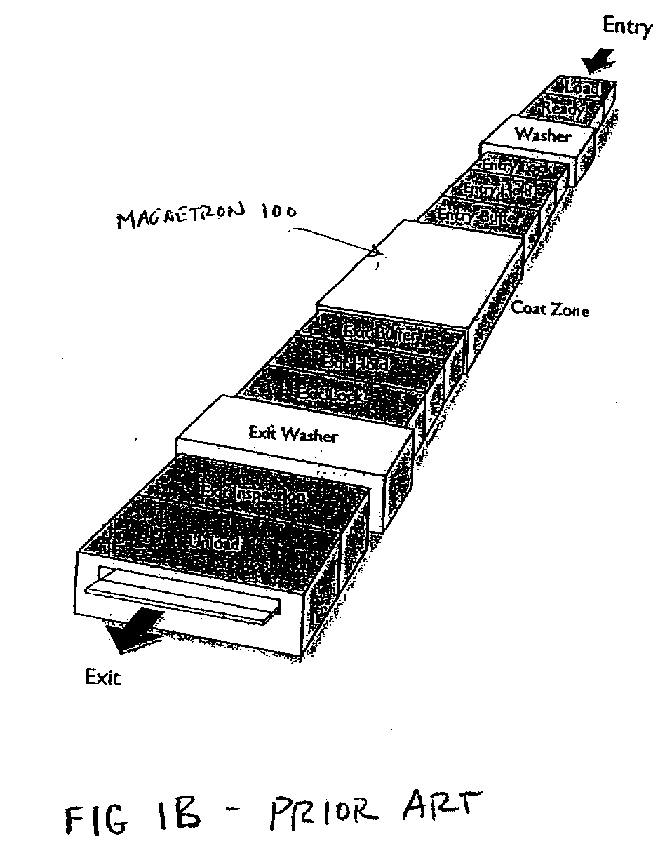
CROSS-REFERENCE TO RELATED APPLICATIONS [0001] This application is a continuation of U.S. application Ser. No. 10 / 840,993, filed on May 7, 2004, which is a continuation of U.S. application Ser. No. 10 / 052,732, filed on Jan. 18, 2002, now U.S. Pat. No. 6,736,948, issued on May 18, 2004. Each of the foregoing applications is incorporated herein in its entirety by this reference.BACKGROUND OF THE INVENTION [0002] The cylindrical magnetron is used in a large coating machine for coating very large sheets of glass or other materials. One application where these sheets of glass are used is in construction of curtain wall buildings where a single glass sheet can be up to 15 feet wide by about 20 plus feet high. The sheets are run through the coating machine shortly after the glass is manufactured. Thus, these are large-scale machines which must rapidly and evenly coat glass as quickly as it can be manufactured. In addition to the quality of the coating the magnetron deposits upon the glass,...

Claims


Application Information

Patent Timeline
Patent Type & Authority Applications(United States)
IPC IPC(8): C23C14/00H01J37/34
CPCH01J37/3435H01J37/3405
Inventor BARRETT, RICHARD L.
Owner VON ARDENNE ANLAGENTECHNIK GMBH
Why Eureka
Try Eureka