Door handle device and keyless entry device having the same

a door handle and keyless entry technology, applied in anti-theft devices, program control, instruments, etc., can solve the problems of not being able to enter the sensor, not being able to operate the switch by a light touch, and unable to achieve the effect of making the user's door opening/closing operation easy

Inactive Publication Date: 2006-10-19
PANASONIC CORP
View PDF5 Cites 49 Cited by
  • Summary
  • Abstract
  • Description
  • Claims
  • Application Information

AI Technical Summary

Benefits of technology

[0088] Accordingly, the same advantages as those in the invention set forth in claim 22 can be achieved. Also, when this keyless entry system is installed in the building, or the like, the door opening operation or the door opening / closing operation applied from the outer side and the inner side to get on and off is made easy at a timing at which the door locking means is opened an closed, and the house of which the operator goes on and off smoothly can be provided.
[0089] The door opening / closing device of the present invention makes it possible to open or shut the door lock by the door opening operation or the door opening / closing operation applied from either of the outer side and the inner side, and it is possible to make the user's door opening / closing operation easy.

Problems solved by technology

However, the contact-connecting switch used in the door handle device in the prior art has such a disadvantage that the switch is not operated by a light touch such as a mere contact, or the like.
Also, since a stroke is needed to connect the contacts, a time difference occurs inevitably between a moment at which the switch is touched and a moment at which the switch starts to operate, which acts as a factor to make a response worse.
For example, in case the door is opened sharply by gripping and pulling the door handle, either the locking state is still kept or the rattling is caused because the unlocking of the locking means is not enough.
Therefore, the user must wait a predetermined time after he or she grips the door handle and then pull the door handle, which has an adverse effect on an operation feeling.
In contrast, the electrical capacitance sensor is easily influenced by the disturbance because the electrodes must be provided on the surface in construction, and thus the noise is ready to enter into the sensor.
Also, since an electrostatic capacity is different according to the person and also is changed by the shoe being put on, the sensor had the problem that a sensitivity control is extremely difficult.
Therefore, a frequency of occurrence of a malfunction is high and thus this sensor has not been put to practical use yet.
When there is a restriction on the space of the sensor arrangement, such a problem exists that the piezoelectric sensor cannot be arranged and fitted in the desired location.
But a malfunction is often caused due to dusts adhered to the sensor, weather conditions such as a rain, a snow, and the like, etc., and such sensor is not the practical one.
Under such circumstances, in the door handle device using the contact-connecting switch, the electrostatic switch, the normal piezoelectric sensor, or the optical sensor and the keyless entry system equipped with any of these door handle devices, it becomes difficult to achieve favorable operation feeling, operational reliability, and fitting performance.
Therefore, there existed the problem that a shape and a dimension of the handle main body 704 are restricted.
In this case, a size of the inner door handle is increase, and thus it may be predicted that the design is subject to various constraints such that a wide fitting space is needed, and the like.
Thus, the two-stage operation is needed and the door opening / closing operation becomes troublesome.

Method used


Image

  • Door handle device and keyless entry device having the same
  • Door handle device and keyless entry device having the same
  • Door handle device and keyless entry device having the same

Examples


first embodiment

(First Embodiment

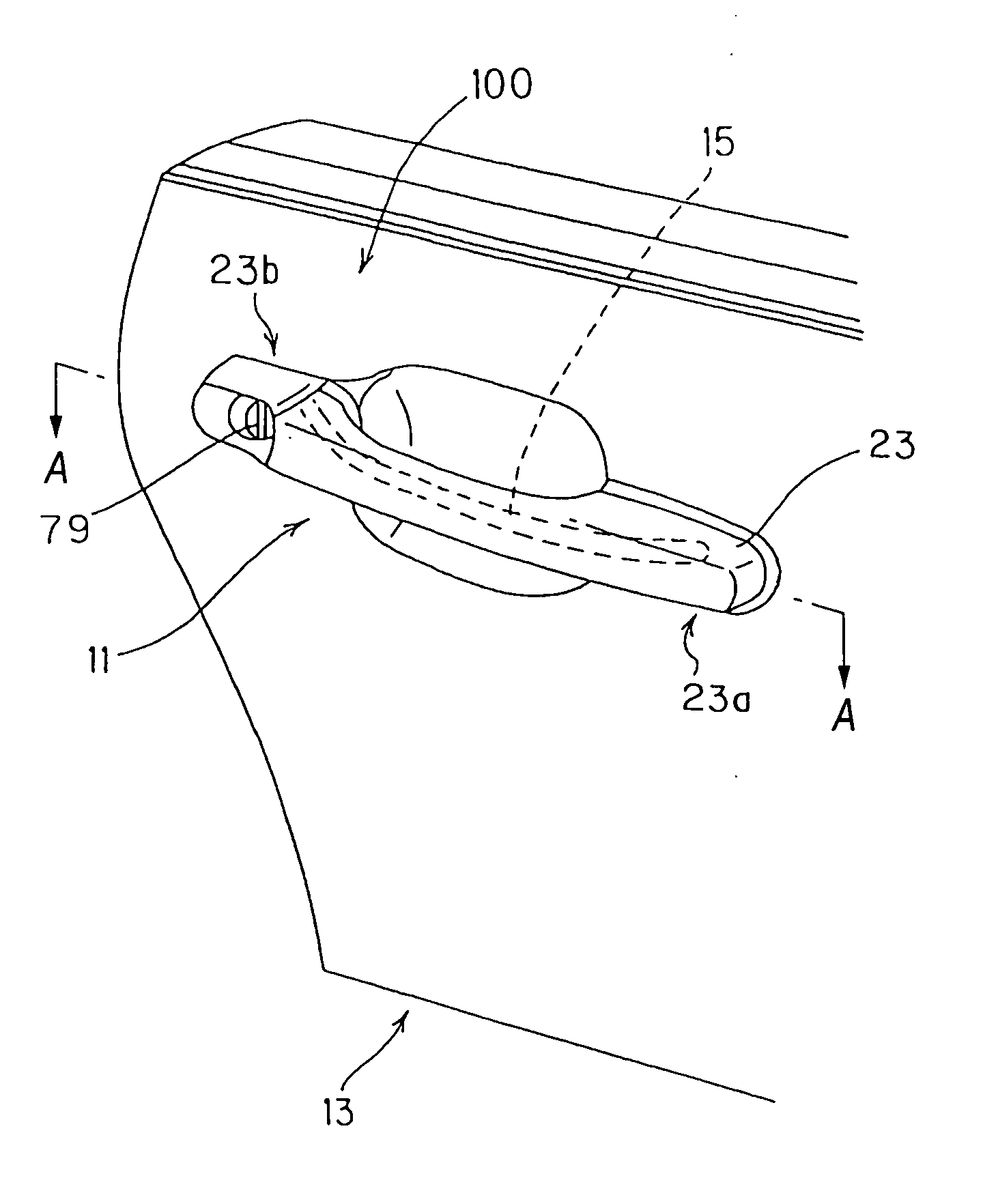
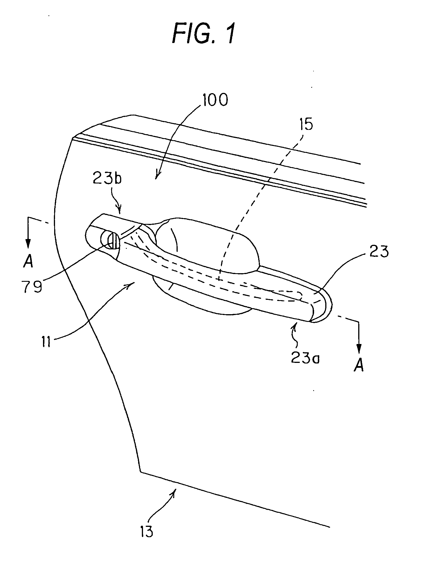
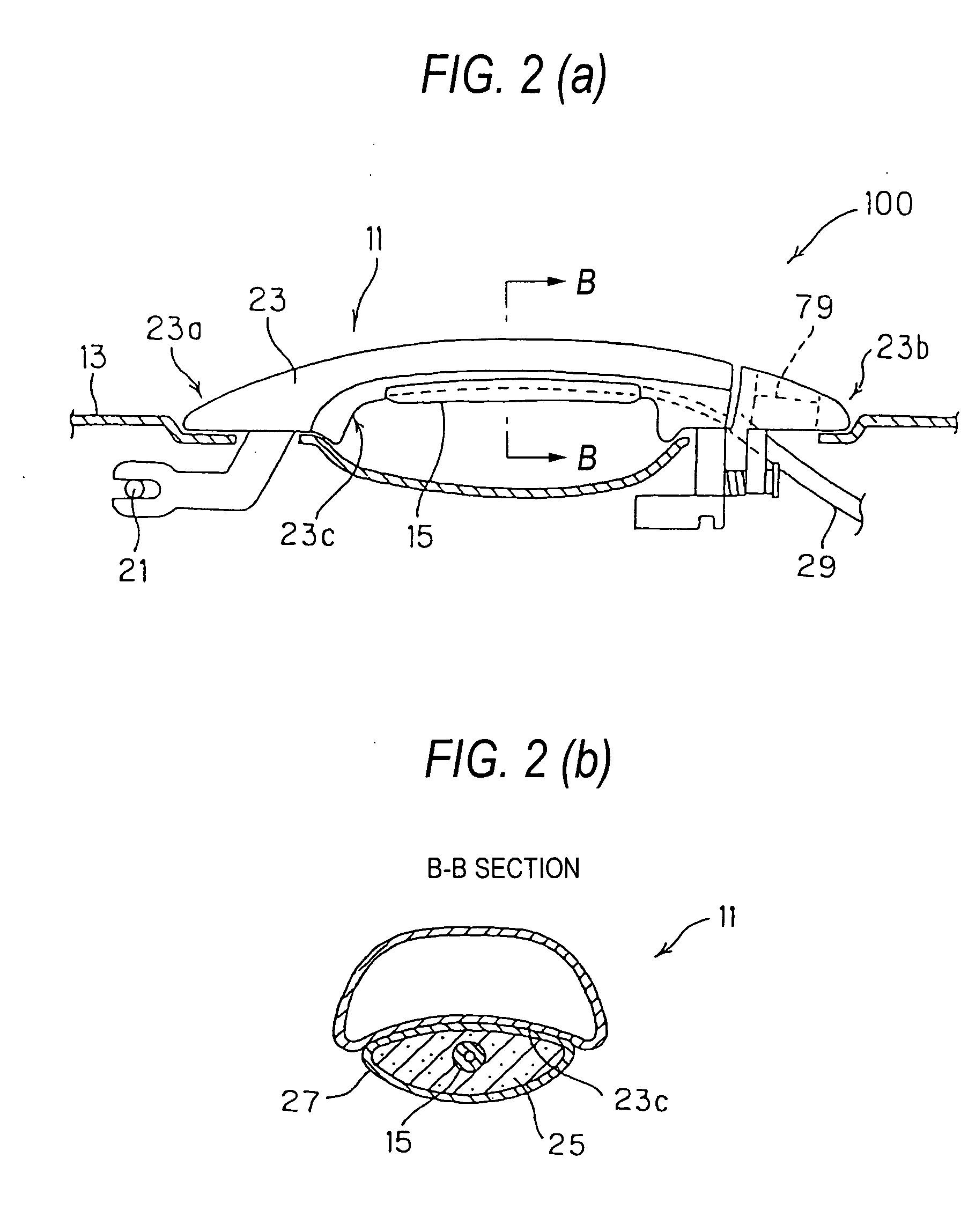
[0132]FIG. 1 is an external perspective view showing a door handle device of a first embodiment according to the present invention. FIG. 2 is an internal configurative view, wherein (a) shows an A-A section in FIG. 1 and (b) shows a B-B section in FIG. 2(a). FIG. 3 is a schematic configurative view of a piezoelectric sensor shown in FIG. 2. FIG. 4 is a configurative view of piezoelectric element material shown in FIG. 2. FIG. 5 is a block diagram of the door handle device.

[0133] As shown in FIG. 1, a door handle device 100 according to the first embodiment is provided to a door 13 having a handle 11 used for the opening / closing operation. A door locking means (not shown) for locking the opening operation of this door 13 can be unlocked by operating the handle 11. The door handle device 100 has a piezoelectric sensor 15 formed of a piezoelectric element provided to the handle 11 and having a flexibility, and a control circuit 17, described later, acting as a control...

second embodiment

[0167] Next, a door handle device of a second embodiment according to the present invention will be explained hereunder. Here, in following embodiments, the same symbols are affixed to the same members or portions as those shown in FIG. 1 to FIG. 9 and their duplicate explanation will be omitted herein.

[0168]FIG. 10 are sectional views showing a door handle device of a second embodiment according to the present invention. FIG. 1 is a view taken along a C-C line in FIG. 10. FIG. 12 is a plan view showing a variation 1 of the second embodiment in which the piezoelectric sensor is arranged near a supporting shaft. FIG. 13 is a plan view showing a variation 2 of the second embodiment in which a top end of the piezoelectric sensor is inserted into an insertion hole of a handle main body. FIG. 14 is a plan view showing a variation 3 of the second embodiment in which the handle main body is constructed as a handle integrated into a door.

[0169] A door handle device 200 according to this e...

third embodiment

[0185] Next, a keyless entry system of a third embodiment according to the present invention will be explained hereunder.

[0186]FIG. 15 is block diagrams showing a keyless entry system of a third embodiment according to the present invention, wherein (a) shows a schematic configuration thereof and (b) shows a principal detailed configuration thereof FIG. 16 is a flowchart showing operational procedures in the keyless entry system shown in FIG. 15.

[0187] A keyless entry system 300 includes any one of door handle devices 100, 200 explained in the first and second embodiments and their variations (for example, the door handle device 100), a transmitter / receiver 91 installed on the vehicle side shown in FIG. 15(a), and a transmitter / receiver 93 carried with the operator. The keyless entry system 300 operates basically to open the lock of the door 13 when the mobile-side transmitter / receiver 93 receives a password request signal that the vehicle-side transmitter / receiver 91 transmits an...


PUM


Abstract

A subject of the present invention is to provide a door handle device capable of controlling its opening/closing action by using a piezoelectric sensor that has a flexible structure and can attain an enough sensitivity even by a light touch, and a keyless entry system having the same.
A door handle device (100) that is able to open a lock of a door locking means, which is provided to a door (13) with a handle (11) used for an opening/closing operation to lock an opening operation of the door (13), by an operation of the handle, includes a piezoelectric sensor (15) formed of a piezoelectric element fitted to the handle (11) and having a flexibility, and a controlling portion for receiving a sensed signal of the piezoelectric sensor (15) generated by a touch on the handle (11) to open the lock of the door locking means.

Description

TECHNICAL FIELD [0001] The present invention relates to a handle device capable of controlling an opening / closing operation by sensing an operation of the handle device by means of a sensor provided to the handle device such as a door handle, or the like, and a keyless entry system having the same. [0002] Also, the present invention relates to a door opening / closing device suitable for a keyless entry system that makes it possible to lock / unlock a door of a vehicle such as a car, or the like without a key operation, and is used for a vehicle door, a building door, or the like. BACKGROUND ART [0003] In unlocking the door lock by operating the door handle of the vehicle, a sensor for sensing a touch or an operation of the handle is provided to the door handle and then a function of unlocking the door lock under predetermined conditions when a sensed signal is output from this sensor is provided. [0004] For example, the vehicle door handle device for unlocking the door lock by using a ...

Claims


Application Information

Patent Timeline
Patent Type & Authority Applications(United States)
IPC IPC(8): B60R25/00B60R25/24E05B65/20G07C9/00
CPCB60R25/246E05B81/78G07C2209/65G07C2009/00373G07C9/00309B60R25/10B60K28/12E05B85/10E05B49/00B60W2530/00
Inventor OGINO, HIROYUKIUEDA, SHIGEKIKANEKO, HIDEKIINUI, HIROFUMI
Owner PANASONIC CORP
Why Eureka
Try Eureka