Eureka AIR delivers breakthrough ideas for toughest innovation challenges, trusted by R&D personnel around the world.

Filled-gap magnetic recording head and method of making

a filling gap and magnetic recording technology, applied in the field of magnetic tape recording heads, can solve the problems of increasing the spacing loss of readback signals, corrosion of giant magnetoresistive (gmr) or magnetic tunnel junction (mtj) sensors when exposed directly to running tape, and achieve the effect of reducing the thickness of the insulation layer

Inactive Publication Date: 2006-10-19
IBM CORP
View PDF12 Cites 135 Cited by
  • Summary
  • Abstract
  • Description
  • Claims
  • Application Information

AI Technical Summary

Benefits of technology

[0012] A method of making the filled-gap magnetic recording head comprises supplying a recording head having a tape support surface including a gap disposed between a rowbar substrate and a closure, intentionally recessing the gap by running a chromium oxide tape over the tape support surface, sputter cleaning the head in a vacuum, depositing an electrical insulation layer on the tape support surface surface and recessed gap, and if desired lapping the tape support surface to reduce the thickness of the insulation layer on the tape supporting regions.

Problems solved by technology

However, the development of small footprint, higher performance tape drive systems has created various problems in the design of a tape head assembly for use in such systems.
Recession of the gap region between the hard ceramic substrate and closure due to tape wear is a problem that results in increased spacing loss of the readback signal.
Another problem that can occur is accumulation of conductive debris and wear material in the recessed region that results in electrical shorting of the magnetoresistive (MR) transducer elements in the gap to other electrically conductive elements in the gap.
Yet another problem is corrosion of giant magnetoresistive (GMR) or magnetic tunnel junction (MTJ) sensors when exposed directly to running tape.

Method used


Image

  • Filled-gap magnetic recording head and method of making
  • Filled-gap magnetic recording head and method of making
  • Filled-gap magnetic recording head and method of making

Examples


Embodiment Construction

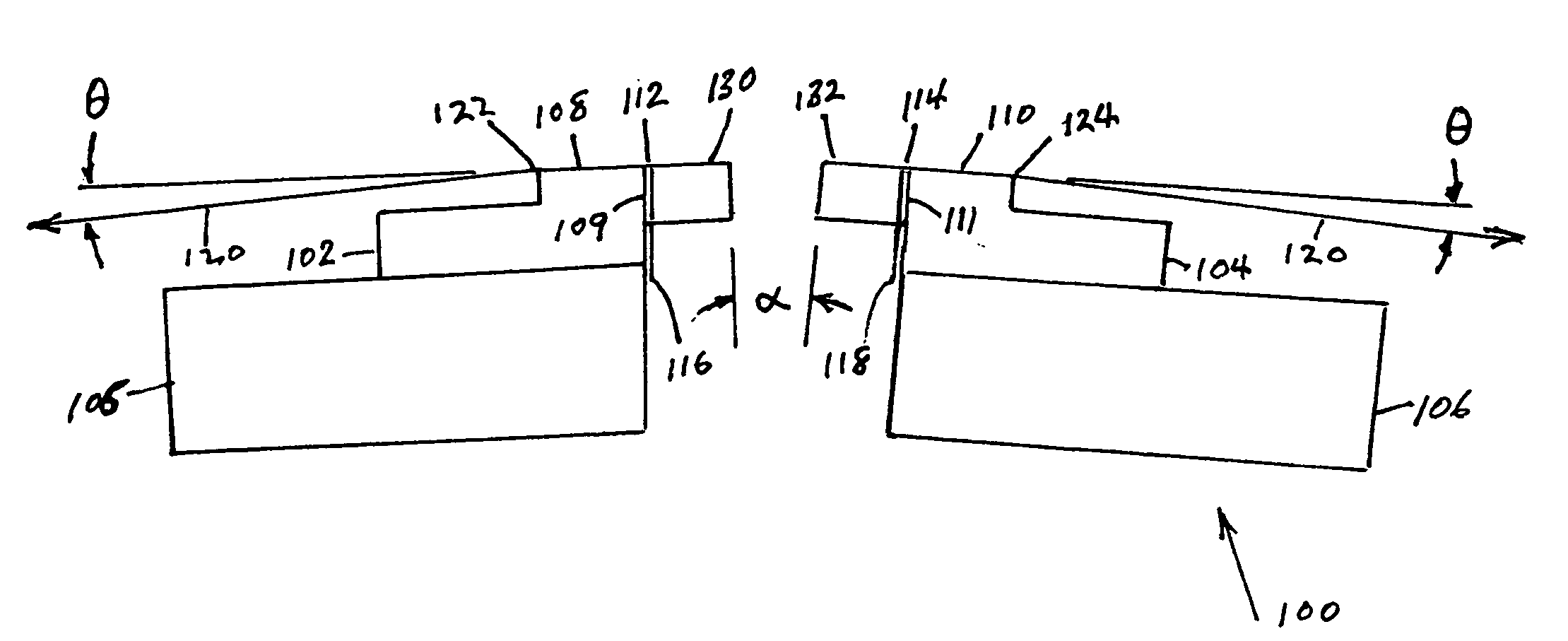
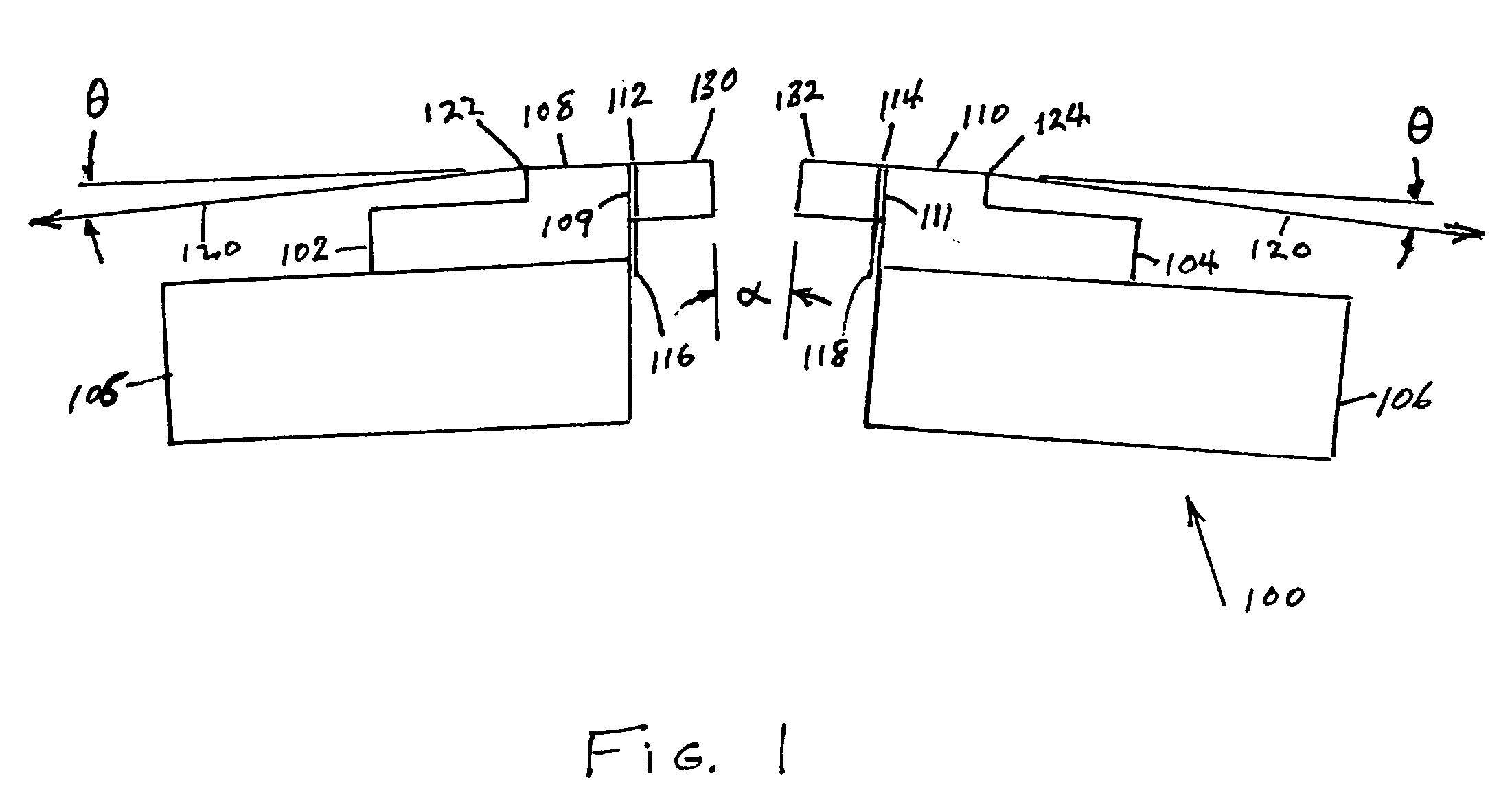
[0025]FIG. 1 illustrates a bi-directional read-while-write flat contour head 100 using the present invention. Rowbar substrates 102 and 104 of a wear resistant material, such as the substrate ceramic typically used in magnetic disk drive heads, are mounted in carriers 105 and 106 fixed at a small angle α with respect to each other. The ceramic rowbar substrates 102 and 104 are provided with flat tape support surfaces 108 and 110 and gap surfaces 109 and 111 and a row of transducers at the surfaces of gap regions 112 and 114. Electrical connection cables 116 and 118 connect the transducers to the read / write channel of the associated tape drive. The wrap angle θ of the tape 120 at edges 122 and 124 going onto the flat tape support surfaces 108 and 110, respectively, and angle α / 2 are usually between ⅛ degree and 4.5 degrees. The rows of transducers are protected by closures 130 and 132 made of the same or similar ceramic as the rowbar substrates 102 and 104.

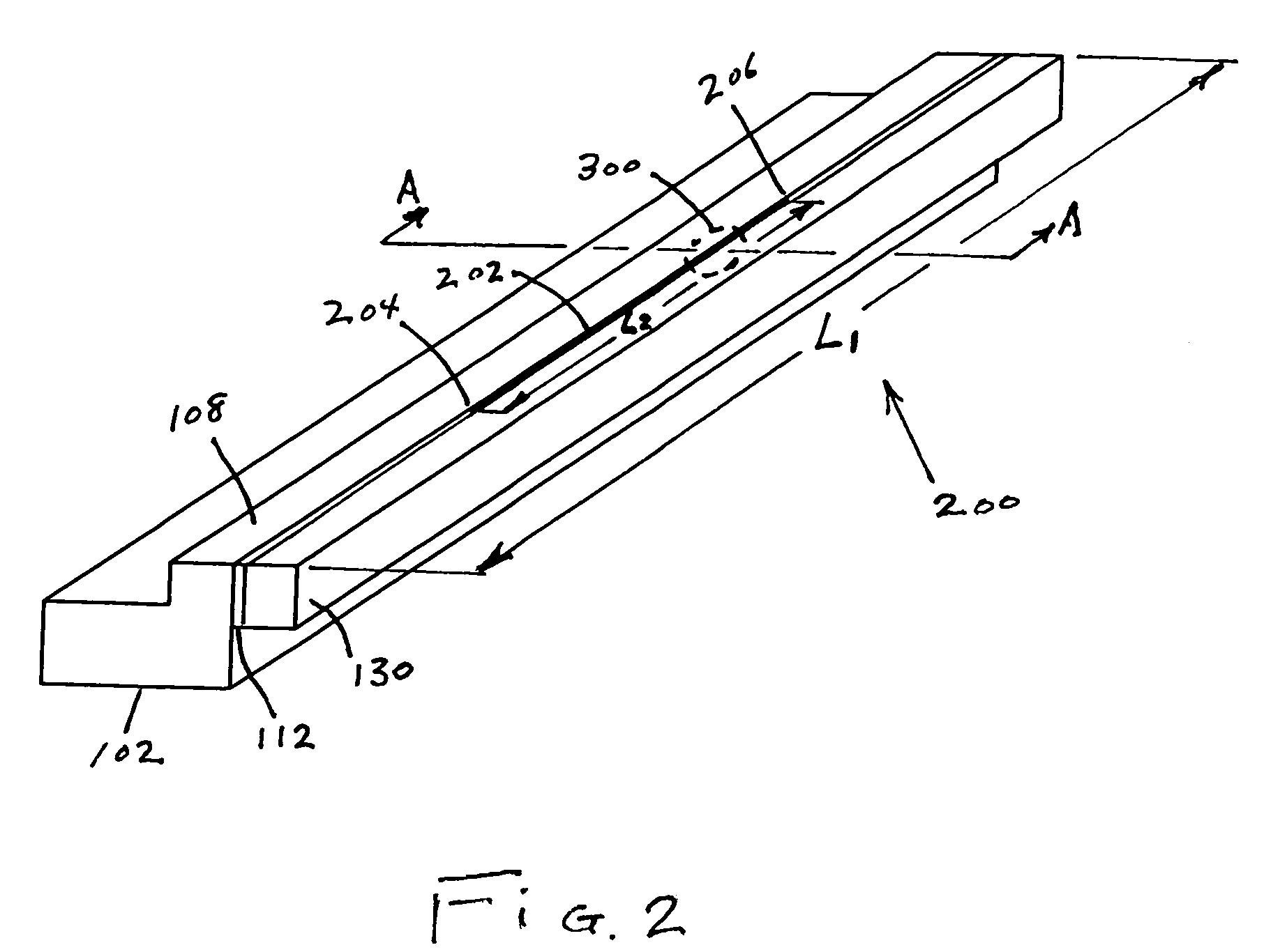
[0026]FIG. 2 is a perspect...


PUM


Abstract

A filled-gap magnetic recording head is provided comprising a flat or cylindrical contour head having a row of magnetic transducers in a gap region disposed between a rowbar substrate and a closure. The gap region is intentionally recessed to have a predetermined recess profile below a tape support surface. An electrical insulation layer is deposited on the tape support surface and on the recess profile of the gap region. The insulation layer prevents electrical shorting between the magnetic transducers and other conductive elements in the gap due to accumulations of conductive debris from the magnetic recording tape. A method of making the filled-gap magnetic recording head by intentionally recessing the gap region, cleaning the recessed profile and depositing an insulator layer is provided.

Description

BACKGROUND OF THE INVENTION [0001] 1. Field of the Invention [0002] This invention relates to magnetic tape recording heads, and more particularly, to a tape recording head having a pre-recessed gap region filled with an electrical insulation material. [0003] 2. Description of the Related Art [0004] In magnetic storage systems, data is read from and written onto magnetic recording media utilizing magnetic transducers commonly referred to as magnetic heads. Data is written on the magnetic recording media by moving a magnetic recording head to a position over the media where the data is to be stored. The magnetic recording head then generates a magnetic field, which encodes the data into the magnetic media. Data is read from the media by similarly positioning the magnetic read head and then sensing the magnetic field of the magnetic media. Read and write operations may be independently synchronized with the movement of the media to ensure that the data can be read from and written to ...

Claims


Application Information

Patent Timeline
IPC IPC(8): G11B5/10
CPCG11B5/00826G11B5/10G11B5/1871G11B5/40G11B5/255G11B5/3106G11B5/23G11B5/00821G11B5/187G11B5/232G11B5/2651G11B5/295G11B5/3169
Inventor BISKEBORN, ROBERT GLENNIBEN, ICKO E.T.LIANG, JASON
Owner IBM CORP
Why Eureka
Eureka Blog
Learn More