Cable and article design for fire performance

a technology of cable and article, applied in the field of electric cables and articles, can solve the problems of increasing the cost of cable installation, and difficulty in practical application of these materials, especially in cable applications, and achieves the effect of increasing the temperature range and low melting poin

Inactive Publication Date: 2006-10-26
NEXANS
View PDF9 Cites 10 Cited by
  • Summary
  • Abstract
  • Description
  • Claims
  • Application Information

AI Technical Summary

Benefits of technology

[0007] According to one aspect, the invention provides a cable comprising at least one conductor, an insulating layer which forms a ceramic when exposed to an elevated temperature and at least one heat transformable layer which enhances the physical properties of the insulating ceramic forming layer when exposed to an elevated temperature.
[0008] The applicant has found that by providing at least one further heat transformable layer, deficiencies in the properties of the ceramic forming layer, during and after exposure to an elevated temperature can be accommodated by this additional heat transforming layer. The provision of this at least one additional layer enhances the overall properties of the cable when the cable is exposed to the elevated temperatures which would normally be experienced in a fire.
[0009] In a preferred form of the invention, the at least one heat transformable layer is co-extruded onto the conductor with the insulating layer. The at least one heat transformable layer may be able to improve, compensate for, or overcome problems associated with the ceramic forming material when used in a cable design.

Problems solved by technology

These tapes have been found to be effective for maintaining circuit integrity in fires, but because of the additional manufacturing steps they are quite expensive to produce.
Further the process of wrapping the tape around the cable is relatively slow compared to other cable production steps and thus, wrapping the tape slows overall production of the cable further adding to the costs.
While the ceramic forming compositions of the prior art, in theory, are able to provide the required electrical and / or thermal insulation, the other physical properties of ceramic forming compositions, both before and after exposure to elevated temperatures, make the practical application of these materials, particularly in cable applications, difficult to implement with compromises needing to be made to accommodate the less than ideal physical properties.

Method used


Image

  • Cable and article design for fire performance
  • Cable and article design for fire performance
  • Cable and article design for fire performance

Examples


example 2

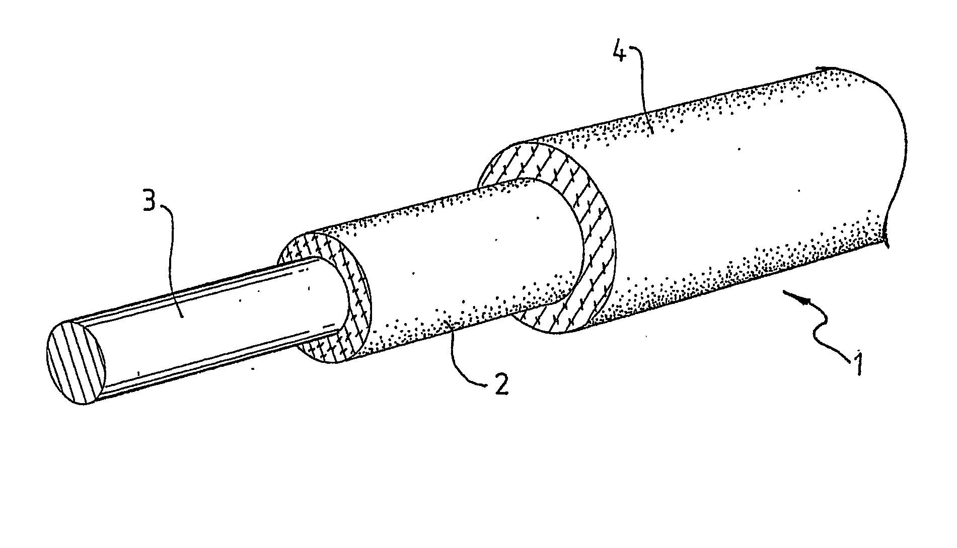
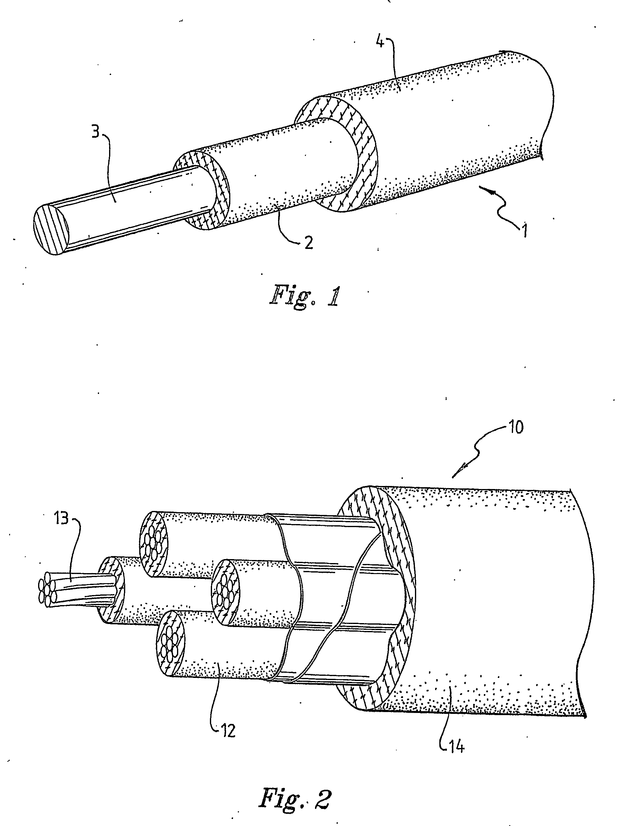
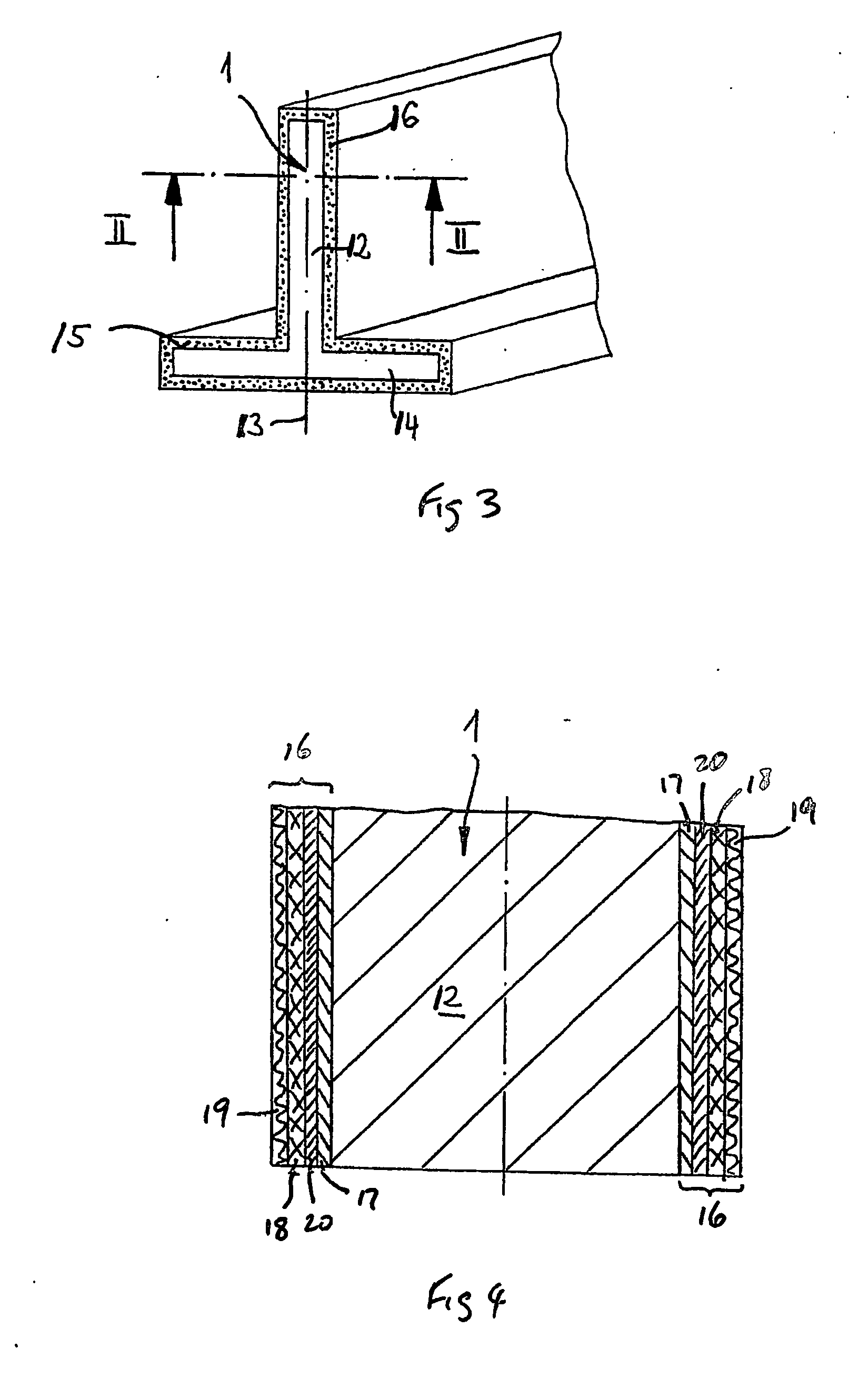
[0110] Three 200 mm sections of 35 mm2 copper conductor were used to make different cable design prototypes. The extrudable compositions examined as sacrificial layers were Composition C (an ethylene propylene rubber heavily filled with predominantly aluminium hydroxide, and containing peroxide) and Composition D (a silicone polymer containing peroxide for thermally induced crosslinking). Composition E (silicone polymer / mica / glass fibre / peroxide 73:20:5:2), which forms a ceramic material when heated at elevated temperatures, was the outer layer in all three prototypes. The prototypes were prepared by simultaneously moulding and curing the composition(s) onto the cable sections. The designs and the layer thicknesses are shown in Table 1.

TABLE 1Sacrificial LayerOuter Layer (CeramicCompositionforming layer) CompositionPrototype(thickness, mm)(Thickness, mm)1NilE(1)2CC(1)E(1)2DD(1)E(1)

[0111] All three prototype cables were then heated in a furnace to 1000° C. in air for 30 minutes. Th...

example 3

[0116] A plain annealed copper stranded conductor made from 19 wires of 1.67 mm2 was electrically insulated simultaneously with a sacrificial layer based on EP polymer and a silicone elastomer based ceramic forming layer of composition E to an overall wall thickness of 1.2 mm. A similar cable was made with just the silicone elastomer based ceramic forming layer and without the sacrificial layer.

[0117] On firing these samples to 1,000° C., it was observed that a full coverage of the conductor was maintained in both cases.

[0118] However, as the samples cooled, the conductor in the sample that did not have a sacrificial layer began to disrupt the ceramic forming layer, due to interactions between the copper oxides of different valence.

[0119] This did not occur with the sample made with the sacrificial layer.

example 4

[0120] An EP polymer based composition was made with 62% of magnesium hydroxide for use as an inner sacrificial layer of high electrical resistance. The Mg(OH)2 was expected to convert to a powder of MgO on exposure to 1,000° C., leaving a powdery mass that did not ceramify.

[0121] Cable samples made with this material included 35 mm2 and 1.5 mm2 plain annealed copper conductors. Testing in a furnace at up to 1,050° C. resulted in the expected conversion of the Mg(OH)2 to MgO and a powdery layer over the conductor, held in place by the outer ceramic forming layer of composition J (given in Table 3). In comparison with other inner layer materials, this layer was found to provide higher electrical resistivity at 1,000° C. by a factor of 2.


PUM

PropertyMeasurementUnit
wt. %aaaaaaaaaa
thicknessaaaaaaaaaa
temperatureaaaaaaaaaa

Abstract

A cable (1) comprises a conductor (3), an insulating layer (2) which forms a self-supporting ceramic layer when exposed to elevated temperatures experienced in a fire, and an additional heat transformable layer (4). The additional layer (4) can be another layer which forms a self-supporting ceramic layer when exposed to fire, or it can act as a sacrificial layer which decomposes at or below the temperature that the insulating layer forms a ceramic. The addition layer can enhance the strength of the layers before, during or after the fire, the structural integrity of the insulting layer (2) after the fire, the resistance of the layers to the ingress of water after the fire, or the electrical or thermal resistance of the layers during and after the fire.

Description

FIELD OF THE INVENTION [0001] This invention relates to electrical cables and articles having at least one ceramic forming layer, insulating or protecting a metal substrate, and, in particular, to the design and manufacture of these cables and articles and their use. BACKGROUND OF THE INVENTION [0002] There are numerous situations where it is desirable to design a product which contains a metal substrate and is resistant to fire. For instance, fire performance cables are required to continue to operate and provide circuit integrity when they are subjected to fire. To meet some of the standards, cables must typically maintain electrical circuit integrity when heated to a specified temperature (e.g. 650, 750, 950, 1050° C.) in a prescribed way for a specified time (e.g. 15 minutes, 30 minutes, 60 minutes, 2 hours). In some cases the cables are subjected to regular mechanical shocks, before, during and after the heating stage. Often they are also subjected to water jet or spray, either...

Claims


Application Information

Patent Timeline
Patent Type & Authority Applications(United States)
IPC IPC(8): H01B3/44H01B3/12H01B3/18H01B7/295
CPCH01B3/12Y10T428/2913H01B7/295H01B3/18Y10T428/31663H01B3/46
Inventor ALEXANDER, GRAEMECHENG, YI-BINGBURFORD, ROBERT PAULMANSOURI, JALEHWOOD, CHRISTOPHERBARBER, KENNETH WILLISRODRIGO, PULAHINGE DON DAYANANDAIVANOV, IVAN
Owner NEXANS
Why Eureka
Try Eureka