Semiconductor device and temperature detection method using the same

a technology of semiconductor devices and temperature sensors, applied in the field of semiconductor devices, can solve the problems of increasing assembly costs, difficult to integrate pressure sensors and temperature sensors while reducing sizes, and increasing carbon dioxide emission amount, so as to facilitate the reduction of size, reduce manufacturing costs, and improve the effect of mass-productivity

Inactive Publication Date: 2006-10-26
FUJI ELECTRIC DEVICE TECH CO
View PDF5 Cites 8 Cited by
  • Summary
  • Abstract
  • Description
  • Claims
  • Application Information

AI Technical Summary

Benefits of technology

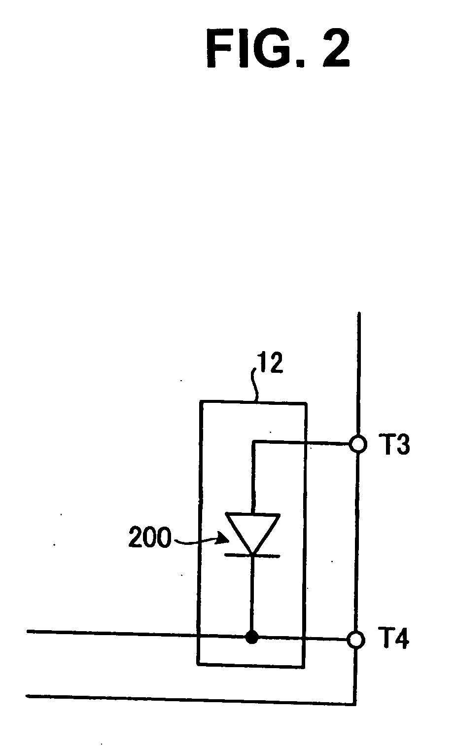
[0025] The semiconductor apparatus according to the invention, which employs one or more diodes having a predetermined structure for temperature detection, facilitates reducing the size thereof, reducing the manufacturing costs thereof, and improving the mass-productivity thereof.

Problems solved by technology

Recently, the restrictions on the carbon dioxide emission amount and such environmental loads have become more severe year by year.
However, since the thermistor and the pressure sensor are individual component parts, it is difficult to integrate the pressure sensor and the temperature sensor while reducing the sizes thereof.
Moreover, many component parts increase the assembly steps, further increasing the assembly costs.

Method used


Image

  • Semiconductor device and temperature detection method using the same
  • Semiconductor device and temperature detection method using the same
  • Semiconductor device and temperature detection method using the same

Examples


first embodiment

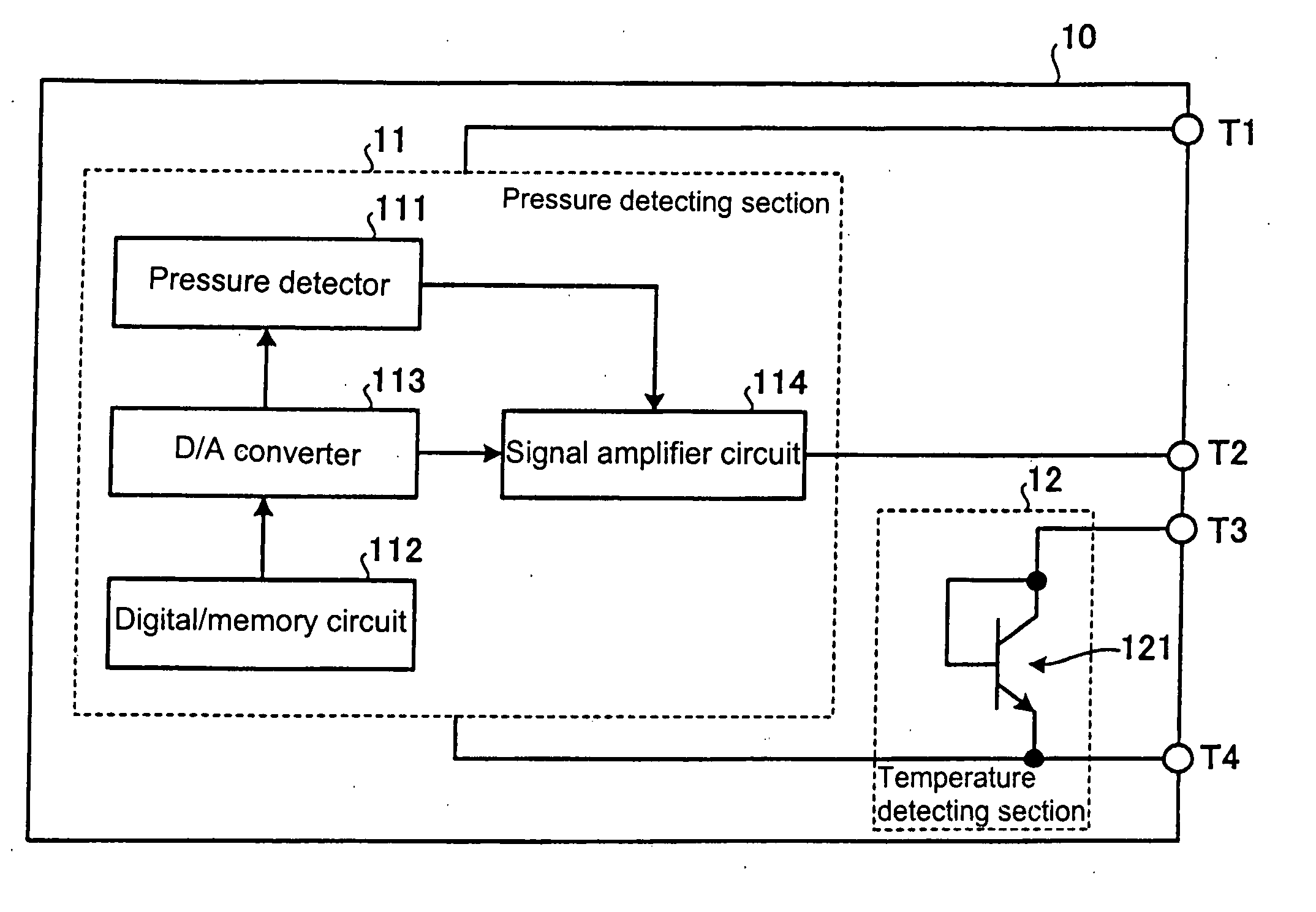
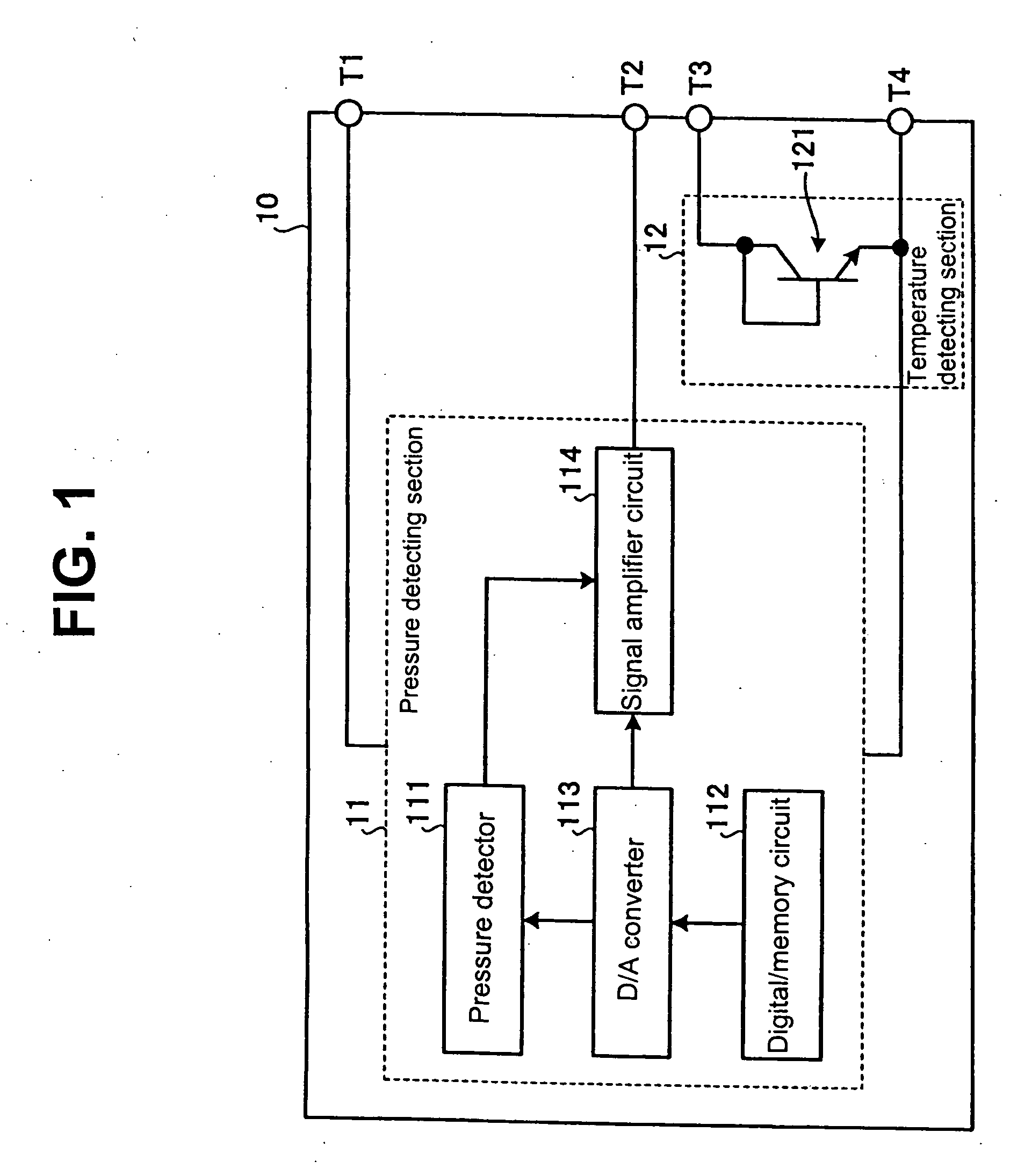
[0048] a p-type semiconductor is used for a substrate. Hereinafter, the substrate made of the p-type semiconductor will be referred to as the “p-type substrate 31.” An n-type well 32, which will work for a collector layer, is formed in p-type substrate 31. A p−-type base layer 331, which will work for a base layer, is formed in the surface portion of n-type well 32. An n+-type emitter layer 362, which will work for an emitter layer, is formed in the surface portion of p−-type base layer 331. A collector is formed of n-type well 32, a base is formed of p−-type base layer 331, and an emitter is formed of n+-type emitter layer 362 such that an npn-transistor (npn-transistor 121) of the so-called lateral-type is formed.

[0049] The term “p+-type” indicates that the impurity concentration for providing a p-type semiconductor with holes is high. The term “p−-type” indicates that the impurity concentration for providing a p-type semiconductor with holes is low. The term “n+-type” indicates ...

second embodiment

[0088] Since the forward voltages Vf's of the diodes are added by connecting, in series, npn-transistors 121 through 125, the respective bases and the respective collectors thereof are short-circuited with each other, it is possible to set the change of the diode forward voltages Vf's caused by a temperature change (the temperature coefficient) to be five times as high as the temperature coefficient for one npn-transistor. In other words, semiconductor apparatus 20 facilitates improving the sensitivity of the temperature sensor. Zener diode 13, which conducts a Zener operation when surges are inputted from the outside, facilitates protecting temperature detecting section 12 against the surges.

[0089] As described above, semiconductor apparatus 20 according to the second embodiment may be used for a composite sensor that exhibits an excellent surge withstanding capability, includes a temperature sensor, the output sensitivity thereof is very high, and facilitates detecting temperatur...


PUM

PropertyMeasurementUnit
driving currentaaaaaaaaaa
temperature coefficientaaaaaaaaaa
absolute temperature coefficientaaaaaaaaaa

Abstract

A semiconductor apparatus has a temperature detecting section for detecting temperature with a semiconductor device formed in a semiconductor substrate; a temperature detector output terminal formed on the substrate for outputting a detection signal; a current generating device connected to the output terminal for supplying a driving current to the temperature detecting section; and a voltage measuring device connected to the output terminal for measuring the voltage of the output terminal. The apparatus detects temperature based on the voltage measured by the voltage measuring device when the driving current is supplied from the current generating device to the temperature detecting section. The apparatus is small, accurate, and easily manufactured at relatively low cost.

Description

BACKGROUND OF THE INVENTION AND RELATED ART STATEMENT [0001] The present invention relates to a semiconductor device that conducts pressure detection and temperature detection mainly for controlling the engine of an automobile or a motorcycle. The present invention also relates to a temperature detection method. [0002] Detection of the pressure and the temperature inside the engine used for an automobile or a motorcycle is indispensable for controlling the engine. FIG. 14 is a cross-sectional view schematically showing an engine for automobiles. The fundamental behaviors of an engine 40 shown in FIG. 14 will be described below. [0003] First, air is fed to a cylinder 49 through an intake manifold 44. Fuel is injected from a fuel injection 46 and fed to cylinder 49 of engine 40 together with the air flowing through intake manifold 44. [0004] In cylinder 49, a piston 50, valves 47 and a spark plug 48 synchronize each other to repeat a series of behaviors consisting of intake, compressi...

Claims


Application Information

Patent Timeline
Patent Type & Authority Applications(United States)
IPC IPC(8): G01N27/00
CPCG01K7/01G01K2205/02H01L27/092H01L2924/0002H01L2924/00B44C5/0446C09D5/08C09D5/16C09D133/00C09D163/00G09F19/22
Inventor NISHIKAWA, MUTSUOUEYANAGI, KATSUMICHI
Owner FUJI ELECTRIC DEVICE TECH CO
Why Eureka
Try Eureka