Microscope

a microscope and microscope technology, applied in the field of microscopes, can solve the problem of not being able to dye a living body desirabl

Active Publication Date: 2006-10-26
EVIDENT CORP
View PDF5 Cites 60 Cited by
  • Summary
  • Abstract
  • Description
  • Claims
  • Application Information

AI Technical Summary

Benefits of technology

[0026] In the microscope according to the present invention, it is desired that the modulation means is constituted of a modulator which modulates the first pulse light and, the detection device is constituted of a lock-in detector. In the microscope according to the present invention, it is desired that a predetermined wavelength band is scanned by the first pulse light and, the second pulse light is fixed to an optimal wavelength for multiphoton excitation. In the microscope according to the present invention, it is desired that it comprises a laser light selection means having a switching means which switches ON/OFF of the first pulsed laser generating means and the second pulsed laser generating means, and a control means to control the laser light selection means.
[0027] In the microscope according to the present invention, it is desired that it comprises an image processing apparatus which processes a signal detected thro

Problems solved by technology

However, it is not desirable to dye a living body by the fluorescence pigment, since it is foreseen that the living body is affected not a little b

Method used


Image

  • Microscope
  • Microscope
  • Microscope

Examples


first embodiment

[0083] Hereafter, embodiments of the present invention will be explained using drawings. In diagrammatic charts of the drawings in the following embodiments, the following expressions are used: SHG denotes second harmonic wave, 2-P denotes multiphoton excitation fluorescence, Anti-Stokes denotes anti-Stokes light, Pump denotes pump light, CSRS denotes coherent Raman scattering light, Stokes denotes Stokes light, CARS denotes the coherent Raman scattering light, and 1-P denotes single photon excitation fluorescence. These symbols are commonly used in each of the following embodiments.

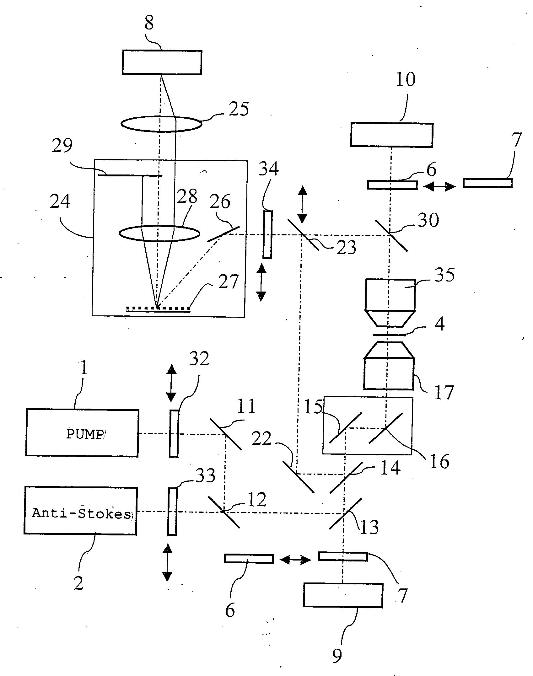
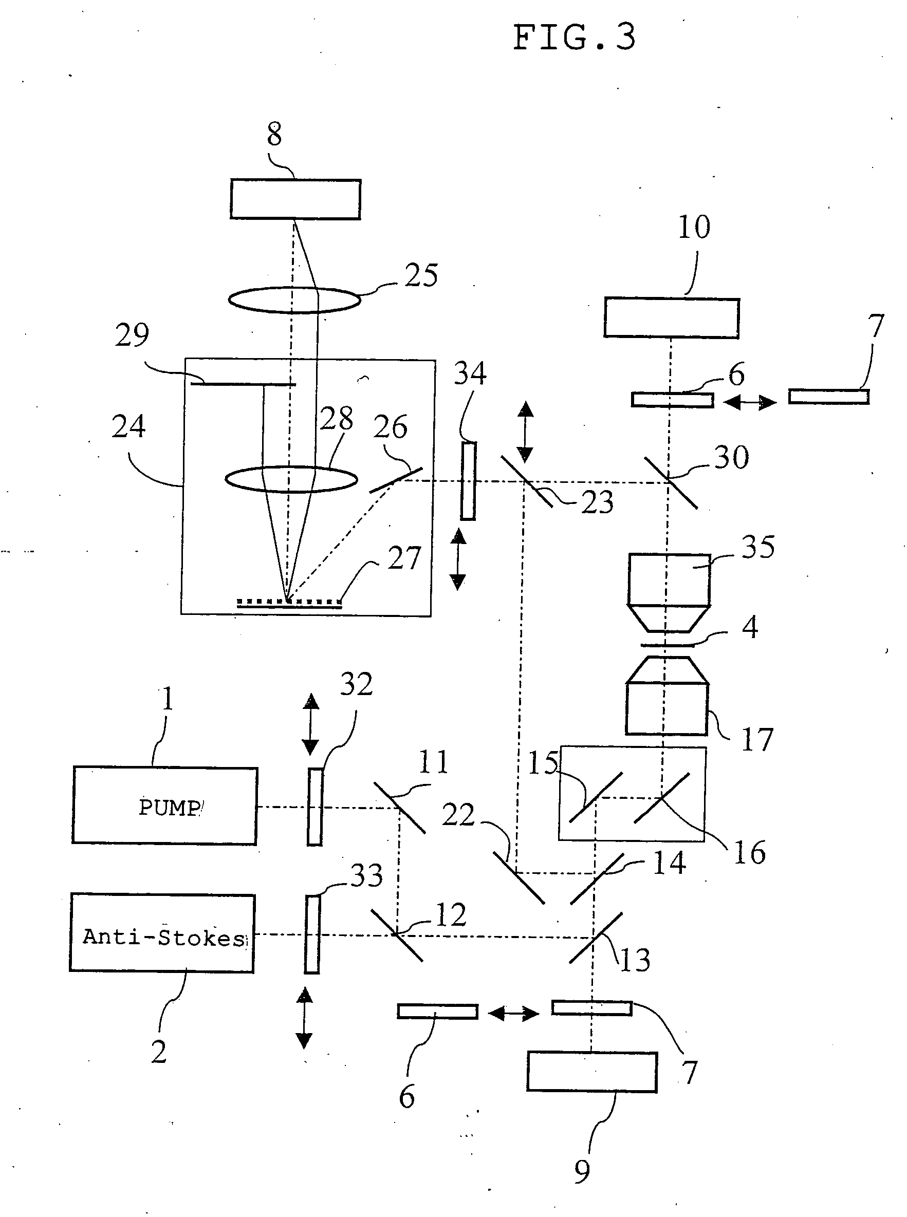
[0084]FIG. 3 is a diagram showing an optical composition of the microscope of the first embodiment according to the present invention. FIG. 4 is a diagrammatic chart showing optical characteristics of a dichroic mirror and a band pass filter used for the microscope in the first embodiment.

[0085] A microscope of the first embodiment comprises a first pulsed laser generating means 1 that generates a firs...

second embodiment

[0124]FIG. 5 is a diagram showing an outlined composition of the microscope system of the second embodiment according to the present invention. FIG. 6 is a diagrammatic chart showing optical characteristics of a dichroic mirror and a band pass filter used for the microscope in the second embodiment.

[0125] In the microscope of the second embodiment, The half mirror 23 is fixed on the optical path where the light reflected by the mirror 22 and the light reflected by the dichroic mirror 30 are crossed, whereby its constitution is limited in such that the coherent Stokes Raman scattering light of both of the F-CSRS light and the E-CSRS light are extracted.

[0126] On an optical path at a penetration side of the dichroic mirror 14, a dichroic mirror 36a is arranged. In the dichroic mirror 13, light having a wavelength of the wavelength band (for example, about 350-450 nm) of the second harmonic wave of the second pulsed laser light transmits, and light having a wavelength longer than tha...

third embodiment

[0129]FIG. 7 is a diagram showing an outlined composition of the microscope system of the third embodiment according to the present invention. FIG. 8 is a diagrammatic chart showing optical characteristics of a dichroic mirror and a band pass filter used for the microscope in the third embodiment.

[0130] The microscope of the third embodiment comprises a first pulsed laser generating means 1′ that generates a first pulse light having a first wavelength component, a second pulsed laser generating means 2′ that generates a second pulse light having a second wavelength component, an irradiation means (symbol is omitted) which is constituted so that irradiation to the specimen 4 can be carried out by composing the first pulse light and the second pulse light, a coherent anti-Stokes Raman scattering light extraction means (symbol is omitted) which extracts only coherent anti-Stokes Raman scattering light from the light emanated from the specimen 4 to which irradiating light is irradiated...


PUM


Abstract

The microscope has a first pulsed laser generating means, a second pulsed laser generating means, an irradiation means to irradiate to a specimen by composing the first pulse light and the second pulse light, a coherent Raman scattering light extraction means for extracting only the coherent Raman scattering light from light emanated from the specimen irradiated, an extraction means for extracting only the multiphoton excitation fluorescence, an extraction means for extracting only the second harmonic wave, a detection means for detecting the extracted coherent Raman scattering light, and a detection means for detecting the extracted fluorescence, and a detection means for detecting the second harmonic wave via the extraction means 7. To single specimen, responding to purposes, observations of the two-photon excitation fluorescence observation, the second harmonic wave observation, and the coherent Raman scattering light observations can be carried out in parallel, or selectively.

Description

[0001] This application claims benefits of Japanese Application No. 2004-199554 led in Japan on Jul. 6, 2004, the contents of which are incorporated by this reference. BACKGROUND OF THE INVENTION [0002] 1. Field of the Invention [0003] The present invention relates to a microscope for observing multi-photon excitation fluorescence, coherent Raman scattering light, second harmonic wave, and the like. [0004] 2. Description of the Related Art [0005] Conventionally, for example, as a microscope aiming at observation of depths in a living, body tissue, for example, a multiphoton excitation fluorescence microscope as shown in the publication of the Japanese unexamined patent application, Toku Kai No. 338405 has been known. For example, as the microscope aiming at observation of a living body tissue, such as collagen which forms a cell membrane, a muscular fiber, and protein sequences, for example, a second higher-harmonic-wave microscope using nano-structural dependence nature of the seco...

Claims


Application Information

Patent Timeline
IPC IPC(8): G01N21/00G01J3/44G01J3/30G01N21/64G01N21/65
CPCG01J3/44G01N21/6458G01N21/636G01N2021/653G01N2021/656G01N21/65
Inventor HASHIMOTO, TAKESHIHAYASHI, SHINICHIKITAGAWA, JUNICHI
Owner EVIDENT CORP
Why Eureka
Try Eureka