
Faraday rotator for high output lasers

a laser and high output technology, applied in the field of faraday rotators, can solve problems such as difficulty in reducing calorific value, and achieve the effect of high isolation effect and excellent isolation function

Inactive Publication Date: 2006-10-26
SUMITOMO METAL MINING CO LTD
View PDF5 Cites 8 Cited by
  • Summary
  • Abstract
  • Description
  • Claims
  • Application Information

AI Technical Summary

Benefits of technology

[0013] The present invention aims at providing a Faraday rotator the isolation function of which is not deteriorated even when the Faraday rotator is used with respect to a laser of a wavelength of not larger than 1.1 μm and a high output of not smaller than 1W without causing the above-mentioned problems to occur.
[0014] The temperature coefficient of the Faraday rotation angle of the RIG film is from around 0.05 degrees / ° C. to around 0.10 degrees / ° C. In order to maintain the isolation function of the optical isolator at not smaller than 30 dB, it is necessary that a temperature rise of the RIG film be held down to around 20° C. to 30° C. Therefore, it is necessary that the calorific power of the RIG film be reduced, and that the heat generated be radiated quickly.
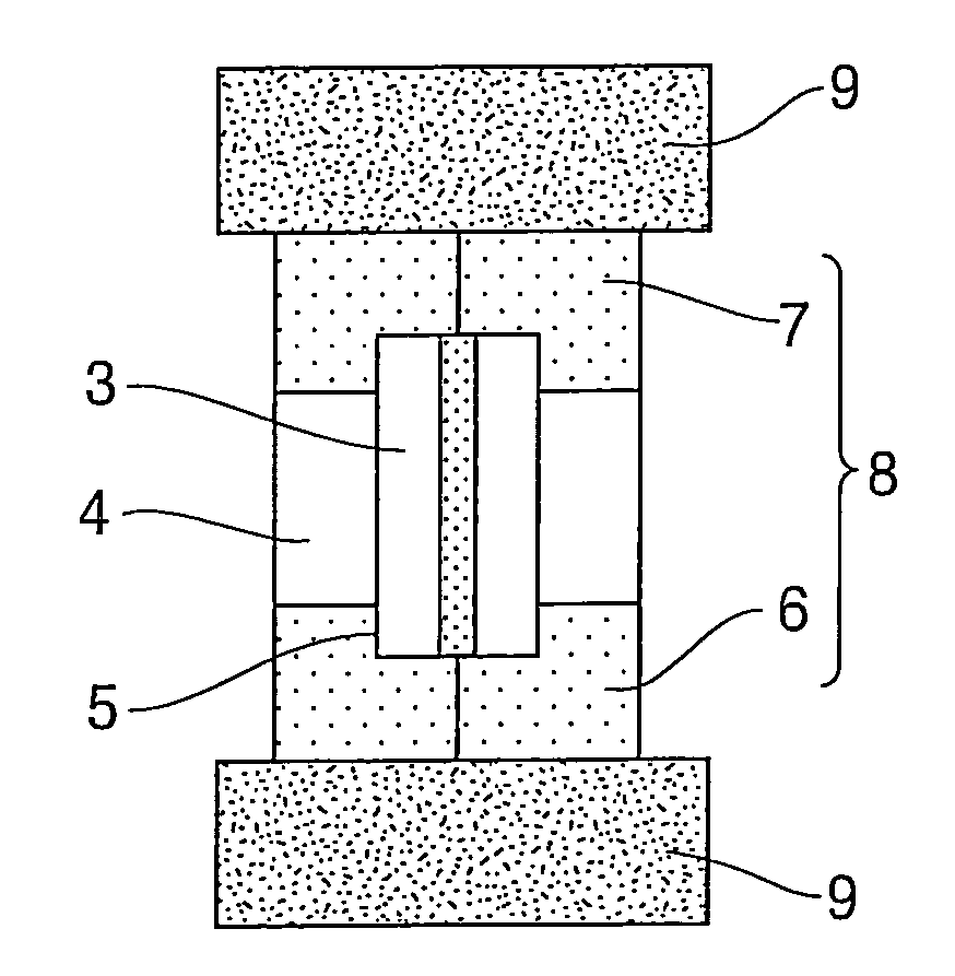
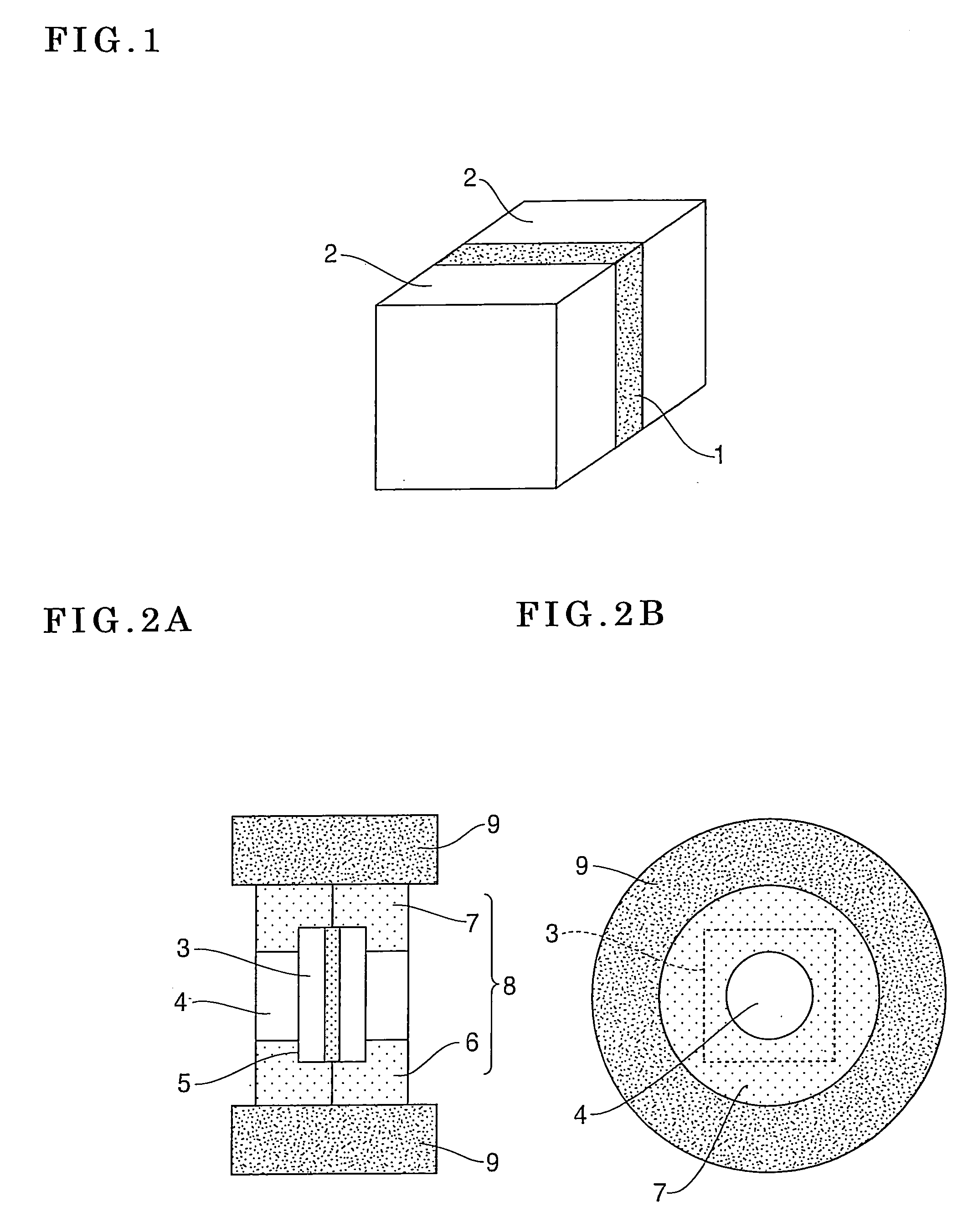
[0019] In view of the above, sapphire crystals or rutile crystals are bonded as a radiation substrate to the incident side and outgoing side of the RIG film, and the thickness of the RIG film is set to not smaller than 130 μm and not larger than 200 μm in the present invention. As a result, the invention succeeded owing to the cooperation of such bonded crystals and thickness-increased RIG film in providing an object Faraday rotator for high output lasers for an optical isolator of an excellent isolation function.
[0020] As described above, it becomes possible to provide when the present invention is used as described above for a miniaturized inexpensive Faraday rotator capable of maintaining a high isolation effect when the invention is used for an optical isolator even though a laser of a high output of not lower than 1W is used for the isolator.

Problems solved by technology

Therefore, it is difficult to reduce the calorific value greatly by substituting iron with Ga and the like with the optical absorption of the RIG film not varied much.

Method used


Image

  • Faraday rotator for high output lasers
  • Faraday rotator for high output lasers
  • Faraday rotator for high output lasers

Examples


example

(Manufacturing of Faraday Rotator)

[0030] The assembling of the Faraday rotator in the embodiment will now be described by using FIG. 1.

[0031] A RIG film 1 of 11 mm×11 mm polished to a thickness of 140 μm so that a Faraday rotation angle becomes 45° with respect to the light of 1064 nm which is the oscillation wavelength of YAG laser, and thereafter applying an anti-reflection coating (not shown) against the bonding glue to both surfaces of the RIG film is prepared. The insertion loss of the RIG film 1 with respect to the light of 1064 nm was 0.6 dB.

[0032] A C-surface sapphire substrate 2 of 11 mm×11 mm and 0.5 mm in thickness identical with the dimensions of the RIG film was used as a radiation substrate. An anti-reflection coating with respect to 1064 nm light was applied to the sapphire substrate as well. An anti-reflection coating for glue (not shown) was provided on the RIG film-bonding surface of the radiation substrate, and an anti-reflection coating for air (not shown) on...


PUM

PropertyMeasurementUnit
thicknessaaaaaaaaaa
thicknessaaaaaaaaaa
thicknessaaaaaaaaaa

Abstract

A Faraday rotator is disclosed, in which the isolation function based on a temperature rise is not deteriorated even when the Faraday rotator is used for a high output laser of not smaller than 1W output at a wavelength of not larger than 1.1 μm. Sapphire crystals or rutile crystals are bonded as radiation substrates to the incident side and outgoing side of a RIG film constituting the Faraday rotator, the thickness of the RIG film being set to not smaller than 130 μm and not larger than 200 μm.

Description

BACKGROUND OF THE INVENTION [0001] 1. Field of the Invention [0002] The present invention relates to a Faraday rotator constituting an optical isolator used as an optical countermeasure against the reflection return beam from a high output laser used for optical communication and processing. [0003] 2. Description of Related Art [0004] When a beam reflected on an optical surface and a processing surface of an outer portion of a laser resonator returns to a laser element in a semiconductor laser utilized for optical communication, a solid laser utilized for laser processing, and the like, the laser oscillation becomes unstable. When the laser oscillation becomes unstable, signal noise occurs in the case of the optical communication, and the breakage of the laser element in the case of the processing laser in some cases. Therefore, in order to intercept such a reflection return beam so that such a beam does not return to the laser element, an optical isolator is used. The optical isola...

Claims


Application Information

Patent Timeline
Patent Type & Authority Applications(United States)
IPC IPC(8): G02B27/28G02B5/30
CPCG02F1/093
Inventor IIDA, JUNJI
Owner SUMITOMO METAL MINING CO LTD
Learn More