
Blood rheology measurement device and blood rheology measurement method

Inactive Publication Date: 2006-10-26
SEIKO INSTR INC
View PDF9 Cites 23 Cited by
  • Summary
  • Abstract
  • Description
  • Claims
  • Application Information

AI Technical Summary

Benefits of technology

[0013] Therefore, as seen from FIG. 11, the blood rheology measurement device of the present invention is capable of measuring the blood rheology of wrist or fingertip with a good precision without, requiring blood pressure measurement. Therefore, it is possible to supply a simple, high-precision, and miniature blood rheology measurement device. As a result, anyone other than a specialist can readily check rheology correctly without sampling the blood from a subject, and the device is usable in checking a health condition.

Problems solved by technology

The measurement is performed by a medical institution only, and anyone cannot readily inspect the health condition anywhere.
The sampling of the blood imposes a large physical and mental burden on the subject, and a limit of the number of times when the measurement can be performed per day is several times at most.
Therefore, there is a problem that data continued in time series cannot be easily obtained.
However, in the method of calculating the blood rheology, that is, the index of the kinematic viscosity of the blood by use of the blood pressure value and the blood flow rate, there is a problem that a measurement error is large because the blood flow pressure in the artery is approximated by means of the blood pressure value.
Furthermore, it is essential to miniaturize the device which measures the blood rheology of a portion such as wrist or fingertip, but this is disadvantageously difficult from viewpoints of a mechanism for the blood pressure measurement, intricacy of the mechanism and the like.

Method used


Image

  • Blood rheology measurement device and blood rheology measurement method
  • Blood rheology measurement device and blood rheology measurement method
  • Blood rheology measurement device and blood rheology measurement method

Examples


Embodiment Construction

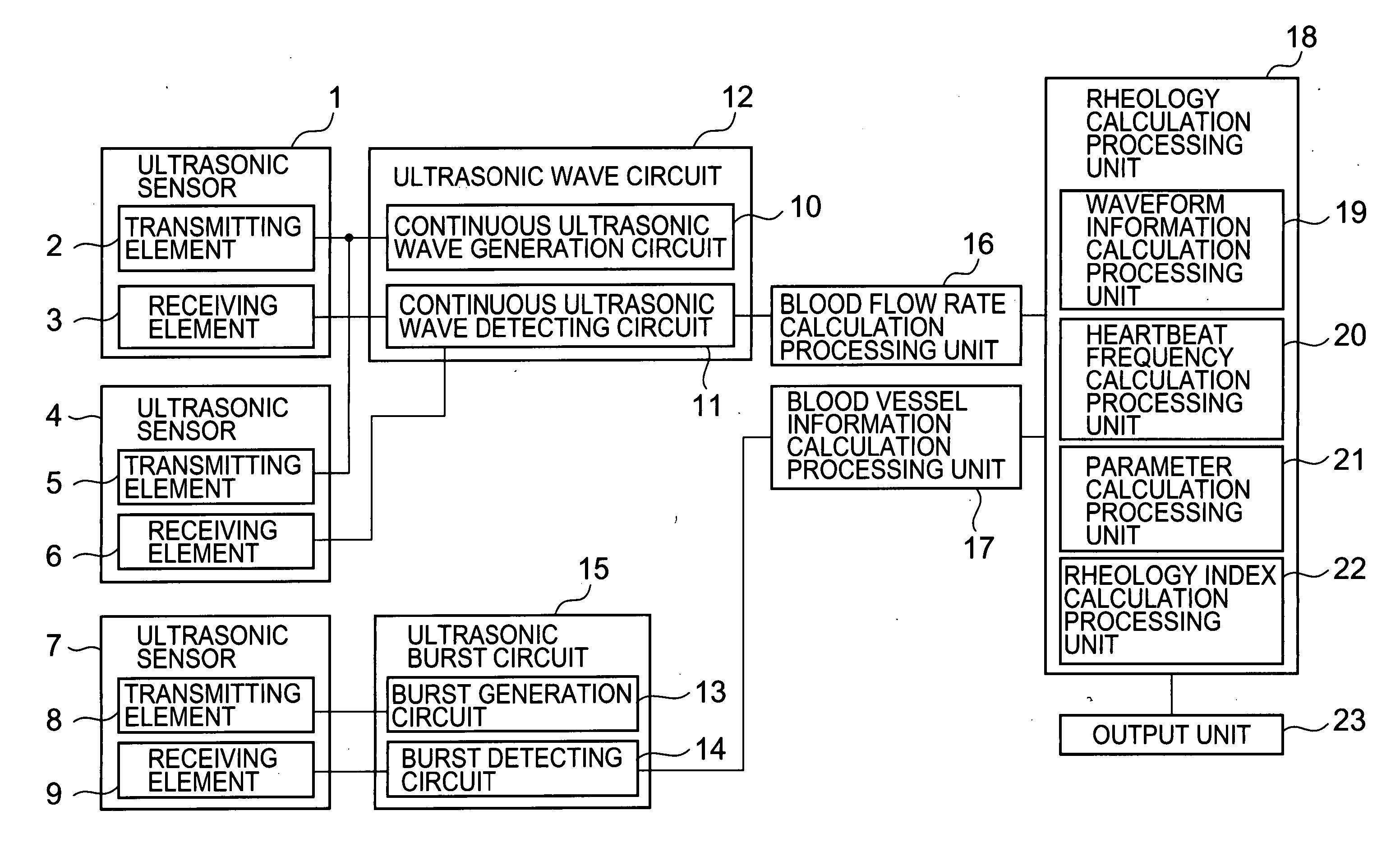
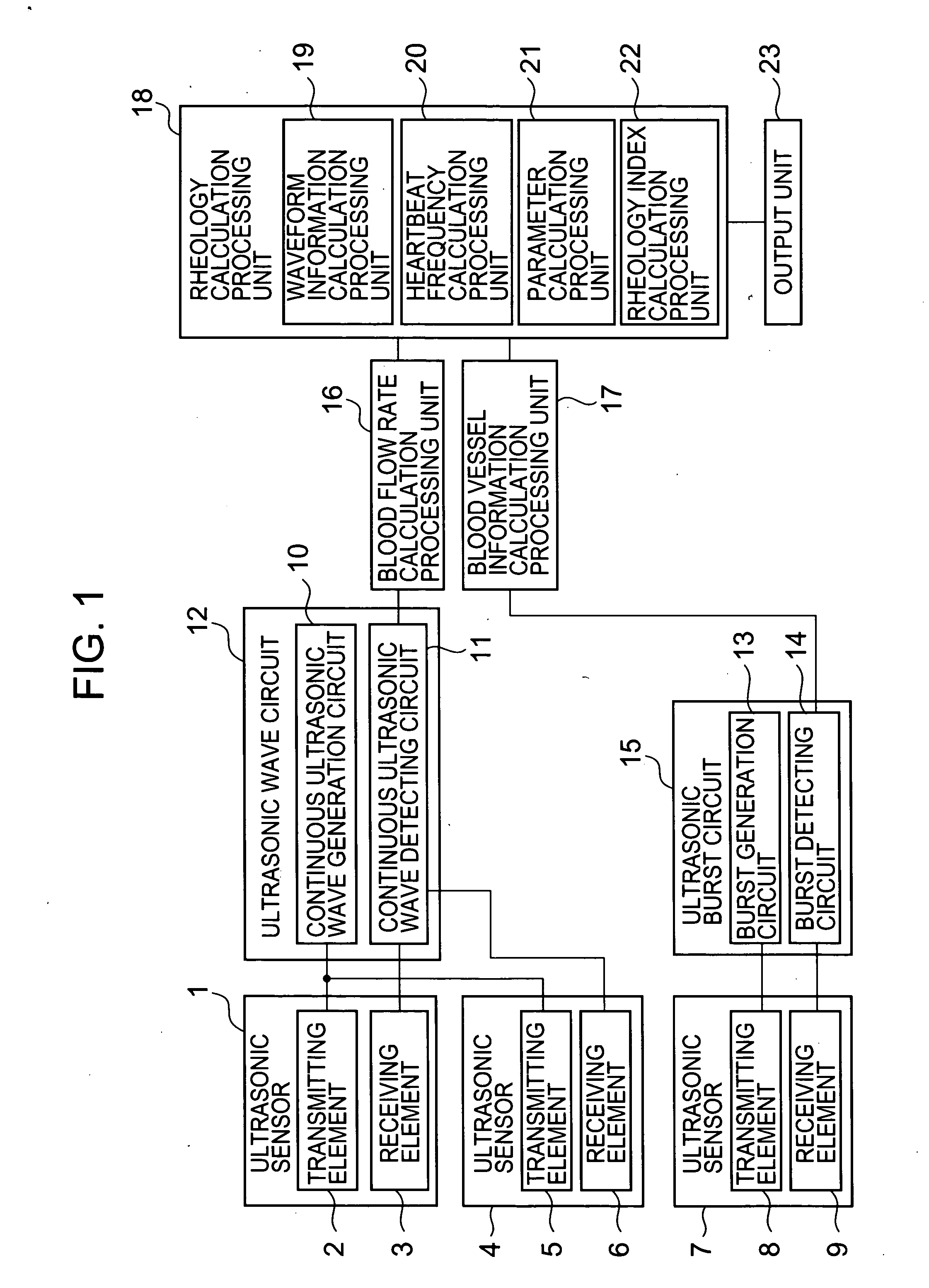
[0048]FIG. 1 shows a block diagram of a constitution of a blood rheology measurement device in the present invention. A sensor unit is constituted of a pair of wave sensors 1 and 4, and an ultrasonic sensor 7 independent of the pair of ultrasonic sensors. The ultrasonic sensor 1 is constituted of a transmitting element 2 and a receiving element 3, the ultrasonic sensor 4 is constituted of a transmitting element 5 and a receiving element 6, and the ultrasonic sensor 7 is constituted of a transmitting element 8 and a receiving element 9. The transmitting elements 2 and 5 are connected to a continuous ultrasonic wave generation circuit 10, an electric signal generated by the continuous ultrasonic wave generation circuit 10 is converted into a mechanical ultrasonic wave, and the ultrasonic wave is transmitted into a living body.

[0049] An ultrasonic signal reflected by a blood flow in an artery and involving the Doppler signal is converted into the electric signal by the receiving eleme...


PUM


Abstract

There is disclosed a miniature blood rheology measurement device and a blood rheology measurement method which are capable of performing measurement of a portion such as a wrist or a fingertip with a high precision and which are simple without requiring measurement of a blood pressure. The method: detects an artery blood flow rate, a pulsatile displacement, an artery diameter, an artery wall thickness, a heartbeat frequency, and a phase difference or an amplitude ratio of the blood flow rate and the pulsatile displacement, which change with elapse of time, by use of a sensor including ultrasonic wave transmitting and receiving elements for transmitting and receiving ultrasonic waves between the surface of a living body and an artery blood flow in the living body; and calculates a blood kinematic viscosity by use of one of the phase difference and the amplitude ratio, the blood vessel diameter, and the heartbeat frequency to obtain an index value of a blood rheology.

Description

BACKGROUND OF THE INVENTION [0001] 1. Field of the Invention [0002] The present invention relates to measurement device and method of a body fluid circulating in a living body, more particularly to a blood rheology measurement device and a blood rheology measurement method for use in grasping a condition of blood to perform evaluation of health, diagnosis of disease, evaluation of effects of medicine and the like. [0003] 2. Description of the Related Art [0004] As one of inspection items for judging a human health condition, there has been noted blood rheology measurement focusing on a fluidity of blood. As means for measuring blood rheology, there is developed a micro channel array type blood fluidity measurement device to measure a time for which a certain amount of blood sampled from a subject passes through a micro channel array (see, e.g., “Measurement of Fluidity of Whole Blood by use of Capillary Blood Vessel Model” by Yuji Kikuchi (Food Research Result Information, No. 11 is...

Claims


Application Information

Patent Timeline
IPC IPC(8): A61B8/00
CPCA61B5/02035A61B8/06A61B8/00A61B8/065A61B8/0891
Inventor KIMURA, FUMIONAKAMURA, TAKAHIKOSHINOGI, MASATAKASUZUKI, MIZUAKI
Owner SEIKO INSTR INC
Learn More