

Differential amplifier circuitry formed on semiconductor substrate with rewiring technique
- Summary
- Abstract
- Description
- Claims
- Application Information
AI Technical Summary
Benefits of technology
Problems solved by technology
Method used
Image

Examples
first preferred embodiment
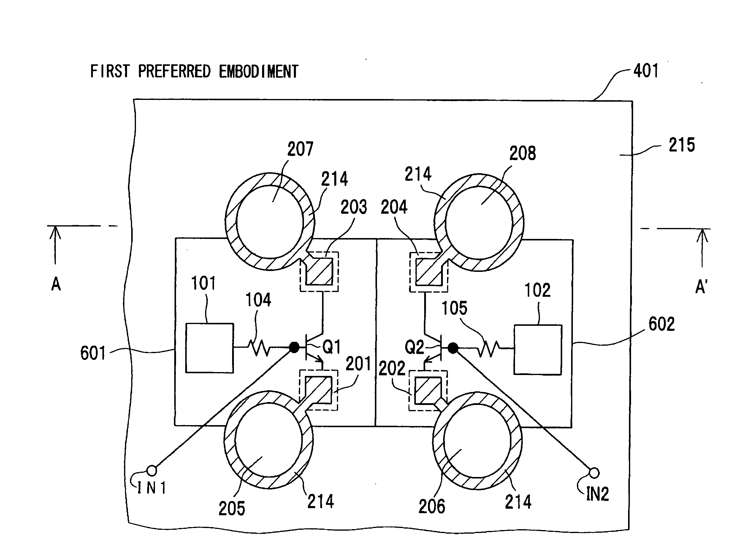
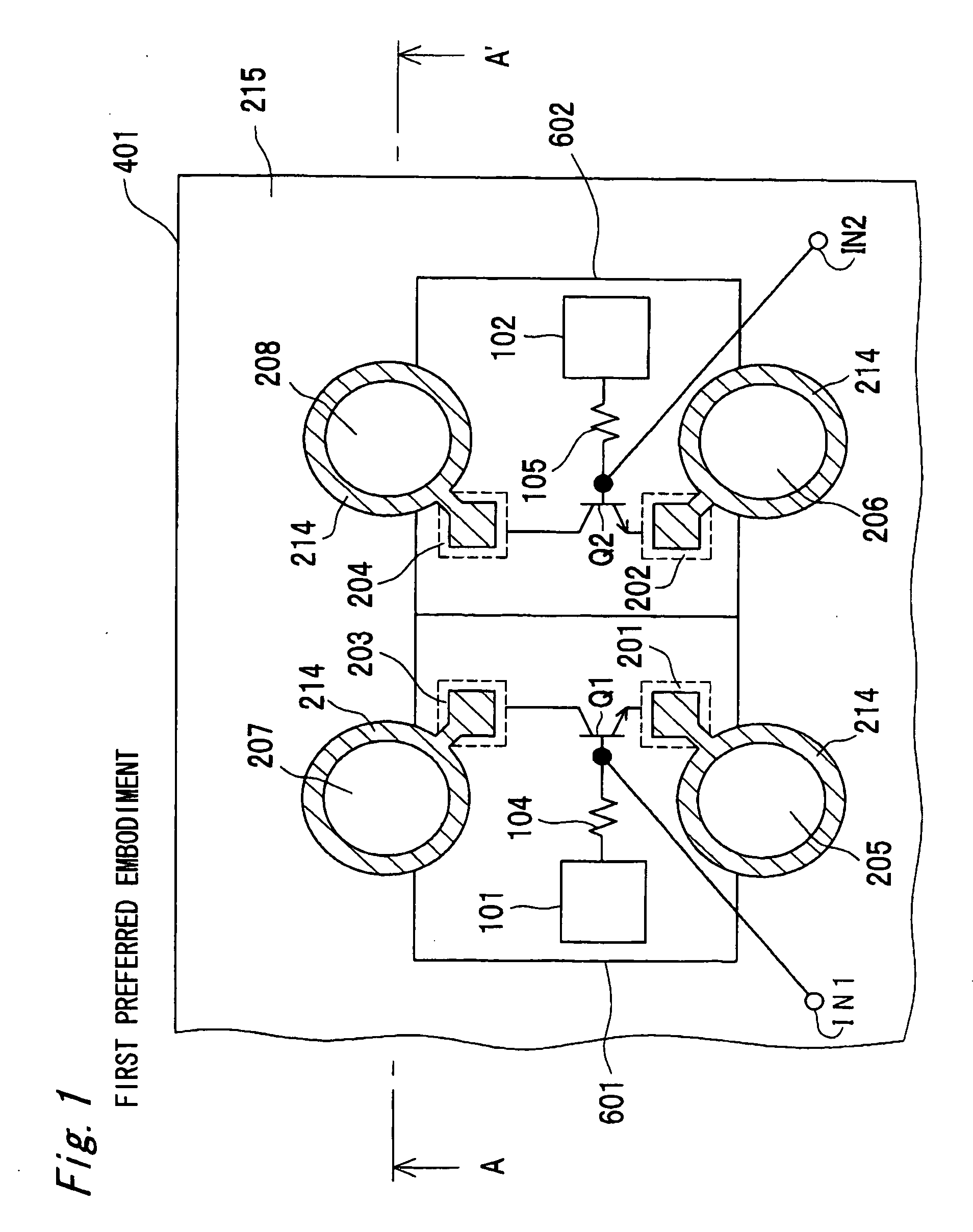
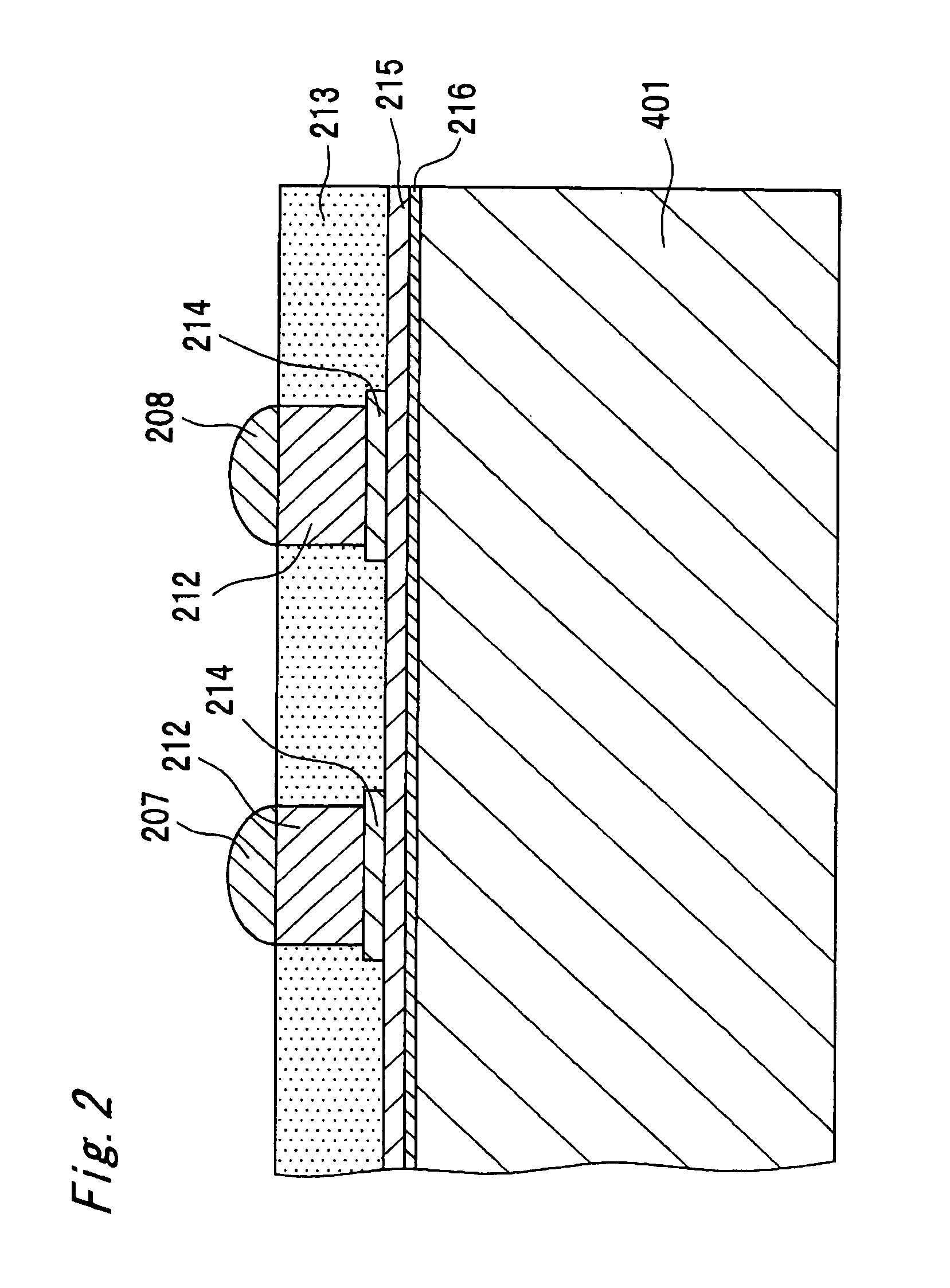
[0033]FIG. 1 is a schematic plan view showing a configuration of a high-frequency differential amplifier circuitry according to a first preferred embodiment of the present invention. FIG. 1 shows a state in which a resin 213 (See FIG. 2) is not formed on a semiconductor substrate 401. The high-frequency differential amplifier circuitry according to the first preferred embodiment is formed on the semiconductor substrate 401 having a chip size package, which forms a rewiring layer on the chip. Referring to FIG. 1, the high-frequency differential amplifier circuitry is configured by including transistors Q1 and Q2, bias circuits 101 and 102, resistors 104 and 105, pads 201, 202, 203 and 204, CSP (chip size package) output terminals 205, 206, 207 and 208, and input terminals IN1 and IN2. The transistors Q1 and Q2 constitute a differential pair. Bases of the transistors Q1 and Q2 are connected with one ends the resistors 104 and 105, respectively, collectors thereof are connected with th...
second preferred embodiment
[0040]FIG. 6 is a schematic plan view showing a configuration of a high-frequency differential amplifier circuitry according to a second preferred embodiment of the present invention. As shown in FIG. 6, the high-frequency differential amplifier circuitry according to the second preferred embodiment is different from that of the first preferred embodiment shown in FIG. 1 in that the CSP output terminals 205 and 206 are connected with each other via the rewiring layer 214. The other respects are similar to those of the high-frequency differential amplifier circuitry according to the first preferred embodiment of FIG. 1, and detailed descriptions of components denoted by the same reference numerals as those of FIG. 1 are omitted.
[0041]FIG. 7 is a cross-sectional view taken along line B-B′ of FIG. 6. Referring to FIG. 7, the CSP output terminals 205 and 206 are connected with each other via the copper post 212, which is formed beneath the respective CSP output terminals 205 and 206, a...
third preferred embodiment
[0043]FIG. 8 is a schematic plan view showing a configuration of a high-frequency differential amplifier circuitry according to a third preferred embodiment of the present invention. As shown in FIG. 8, the high-frequency differential amplifier circuitry according to the third preferred embodiment is different from that of the second preferred embodiment shown in FIG. 6 in that the subcontact 301 is formed in circumference and between of the cells 601 and 602, and that a pad 209 and a CSP output terminal 210 are additionally formed. The other respects are similar to those of the high-frequency differential amplifier circuitry of the second preferred embodiment of FIG. 6, and detailed descriptions of components denoted by the same reference numerals as those of FIG. 6 are omitted.
[0044] Referring to FIG. 8, the subcontact 301 is a grounding conductor, surrounds the cell 601 and the cell 602, and is connected with the pad 209. The CSP output terminal 210 is connected with the subcont...
PUM
 Abstract
Description
Claims
Application Information