Data latch circuit, driving method of the data latch circuit, and display device
- Summary
- Abstract
- Description
- Claims
- Application Information
AI Technical Summary
Benefits of technology
Problems solved by technology
Method used
Image
Examples
embodiment modes
Embodiment Mode 1
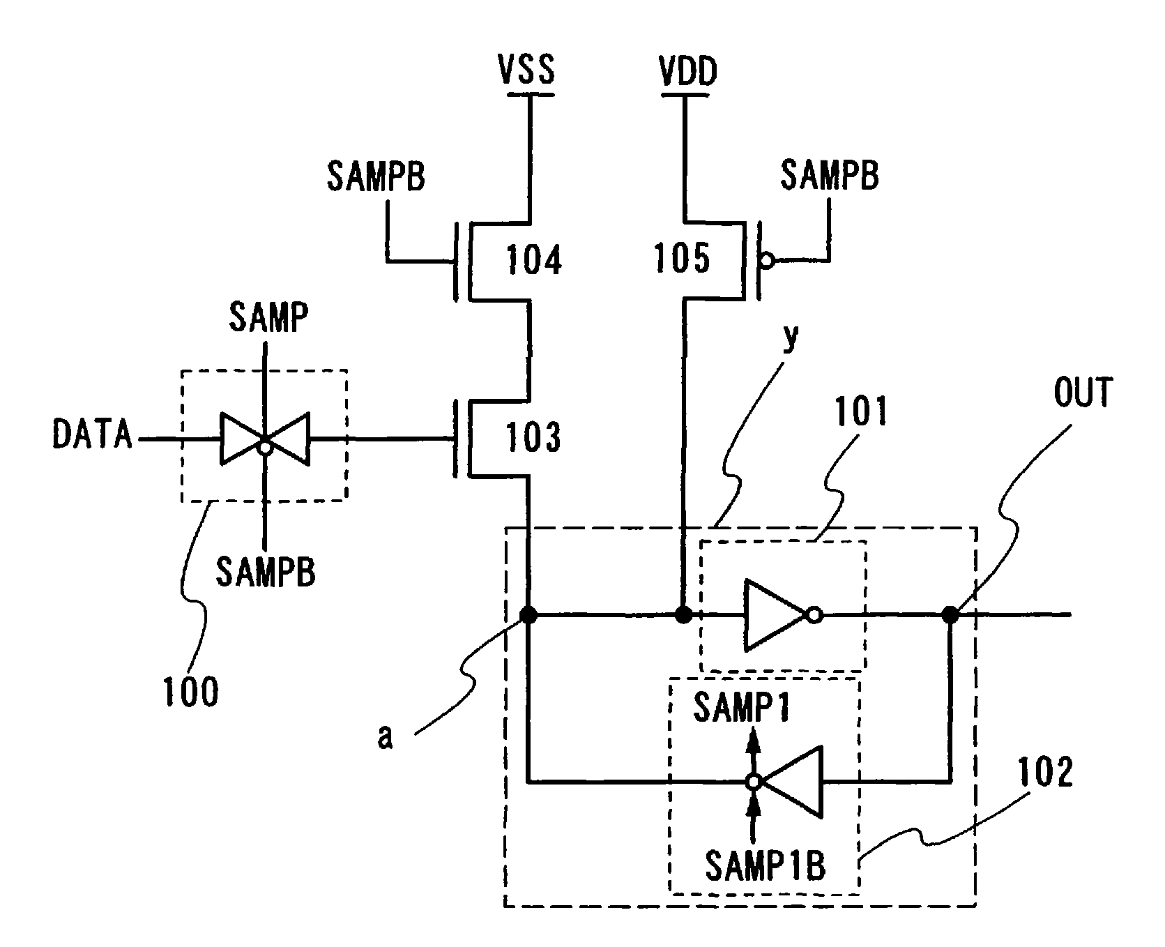
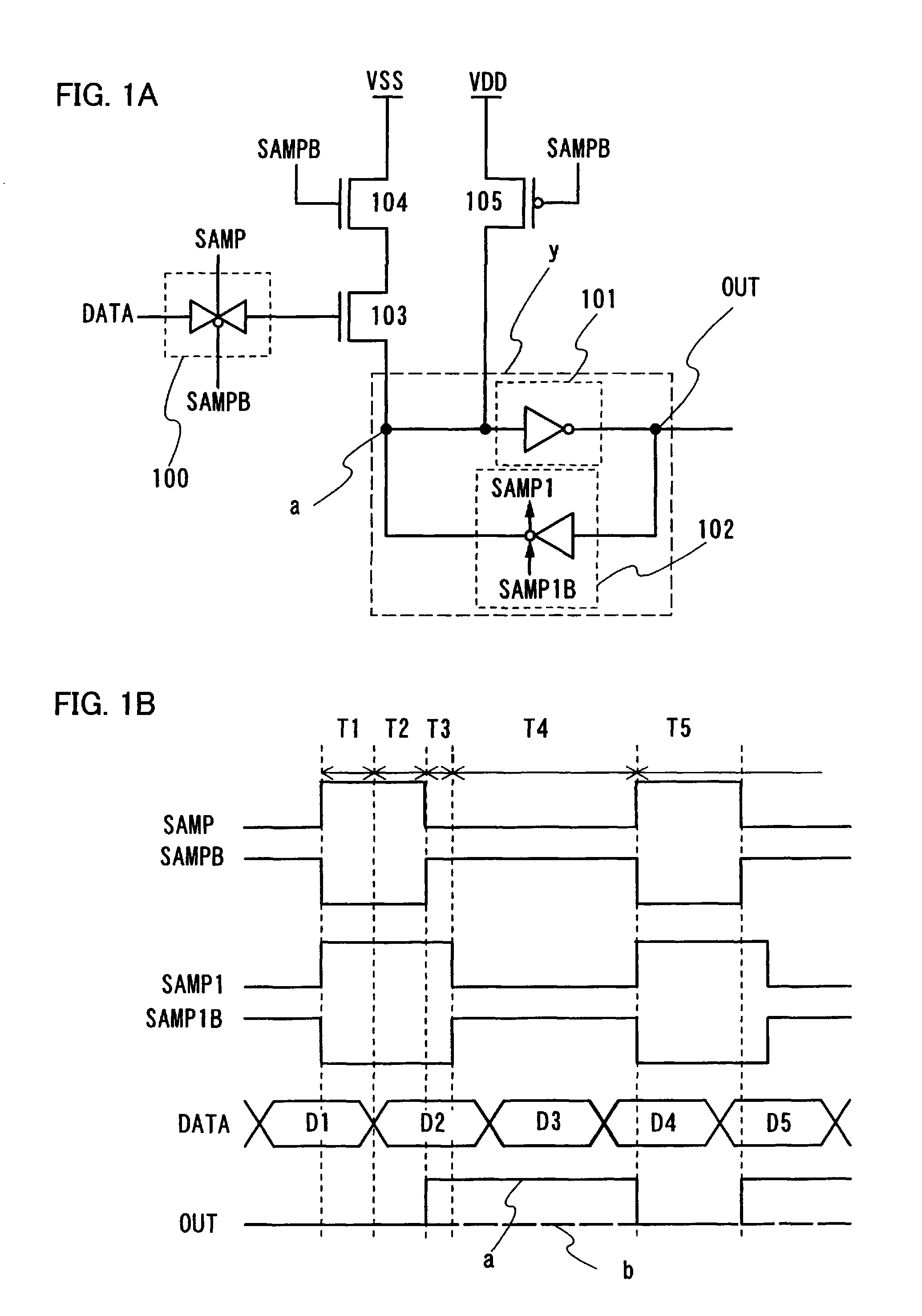
[0035] An embodiment mode of the present invention is hereinafter described with reference to the drawings. In the description of this embodiment mode, the following parameters are used for convenience. It is to be noted that the parameters shown here are one drive condition for a circuit of the present invention, and another combination of different parameters is also allowed as long as a similar operational effect to that in this embodiment mode can be obtained. As a drive power source of the circuit, VSS=0 V and VDD=5 V (5 Vpp) are used. The amplitudes of a sampling (SAMP) signal and an inverted sampling (SAMPB) signal are set at a high (H) level of 5 V and a low (L) level of 0 V (5 Vpp). The amplitudes of a sampling 1 (SAMP1) signal and an inverted sampling 1 (SAMP1B) signal are set at a high (H) level of 5 V and a low (L) level of 0 V (5 Vpp). The amplitude of a data (DATA) signal is set at a high (H) level of 3.3 V and a low (L) level of 0 V (3.3 Vpp). As for...
embodiment mode 2
[0063] This embodiment mode will describe an example of using the data latch circuit employed in this embodiment mode in a source signal line driver circuit. The source signal line driver circuit is to sample a data signal to be inputted and output a signal which has been analog-converted to a source line corresponding to a pixel to be driven.
[0064]FIG. 5 shows an example of a structure of a source signal line driver circuit. The source signal line driver circuit often includes a shift register 600, a latch circuit 601, and a D / A converting circuit (Digital / Analog Converter: DAC) 602. Usually, in the source signal line driver circuit, some level shifters are additionally needed to amplify a data signal when operating the latch circuit; however, the level shifters are not necessary in the present invention. The source lines with the number corresponding to the number of rows of pixels are necessary in the actual source driver; therefore, a source driver portion in a display device i...
embodiment mode 3
[0068] This embodiment mode will describe, with reference to FIGS. 6A and 6B, a display device including the data latch circuit shown in Embodiment Modes 1 and 2, of which a display screen is formed by applying to a pixel a light-emitting element using a material expressing electroluminescence.
[0069] In FIG. 6A, a display panel 1501 has a pixel portion 1503 including a plurality of pixels 1502 arranged in matrix. Each pixel 1502 has a switching element such as a TFT and a light-emitting element connected thereto. A connection wire 1508 which connects an external circuit 1507 and the display panel 1501 may have driver ICs mounted, which form a signal line driver circuit 1505 and a scan line driver circuit 1506. The data latch circuit shown in Embodiment Modes 1 and 2 is incorporated in the driver IC.
[0070] As another mode, the signal line driver circuit 1505 and the scan line driver circuit 1506 can be provided over a substrate where the pixel portion 1503 is formed, as shown in FI...
PUM
 Abstract
Description
Claims
Application Information
 - R&D
- Intellectual Property
- Life Sciences
- Materials
- Tech Scout
- Unparalleled Data Quality
- Higher Quality Content
- 60% Fewer Hallucinations
Browse by: Latest US Patents, China's latest patents, Technical Efficacy Thesaurus, Application Domain, Technology Topic, Popular Technical Reports.
© 2025 PatSnap. All rights reserved.Legal|Privacy policy|Modern Slavery Act Transparency Statement|Sitemap|About US| Contact US: help@patsnap.com


