Optical recording medium and process for producing the same, and data recording method and data reproducing method for optical recording medium

a recording medium and optical recording technology, applied in optical recording/reproducing/erasing methods, instruments, thermography, etc., can solve the problems of increasing and affecting the quality of the recording medium. , to achieve the effect of high storage reliability, reducing the cost of developing and manufacturing the recording/reproducing device, and reducing the cost of production

Inactive Publication Date: 2006-11-02
TDK CORPARATION
View PDF5 Cites 35 Cited by
  • Summary
  • Abstract
  • Description
  • Claims
  • Application Information

AI Technical Summary

Benefits of technology

[0019] Therefore, the object of the present invention is to provide an optical recording medium which enables formation of record marks by means of generation of a chemically-stable gas, and particularly, an optical recording medium of super-resolution type and a method for manufacturing the same.

Problems solved by technology

For this reason, the optical recording medium of the next-generation type encounters difficulty in forming various types of functional layers, such as the recording layer, on the light-transmitting substrate as in the case of a CD, a DVD, an optical recording medium of a current type, and the like.
However, if the wavelength of the laser beam is shortened further, absorption of the laser beam in the light-transmitting layer will abruptly increase, or age deterioration of the light-transmitting layer will become greater.
For these reasons, further shortening of the wavelength is difficult.
Additionally, in consideration of difficulty in the design of a lens, assurance of a tilt margin, or the like, a further increase in the numerical aperture of the objective lens is also difficult.
In short, a further reduction in the size of the laser beam spot can be said to be extremely difficult.
Specifically, in an ordinary optical recording medium which is not of an super-resolution type, if the length of the shortest record marks or the length of the shortest blank region falls below the resolution limit, discriminating between the record marks and the blank region becomes difficult.
However, the reason why data can be reproduced from the thus-formed minute record marks has not yet been elucidated.

Method used


Image

  • Optical recording medium and process for producing the same, and data recording method and data reproducing method for optical recording medium
  • Optical recording medium and process for producing the same, and data recording method and data reproducing method for optical recording medium
  • Optical recording medium and process for producing the same, and data recording method and data reproducing method for optical recording medium

Examples


embodiments

[0104] Embodiments of the present invention will be described hereunder. However, the present invention is not limited to the embodiments.

[0105] [Manufacture of Samples]

first embodiment

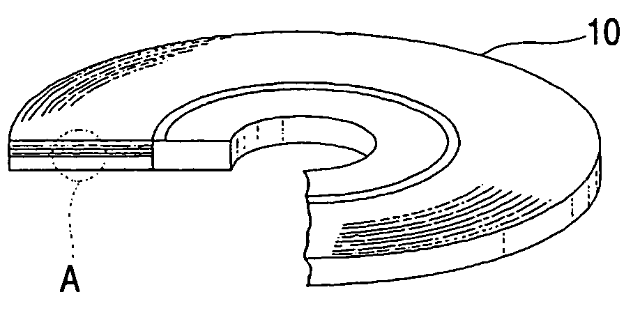
[0106] An optical recording medium sample having the same structure as that of the optical recording medium 10 shown in FIG. 1 was manufactured by the following method.

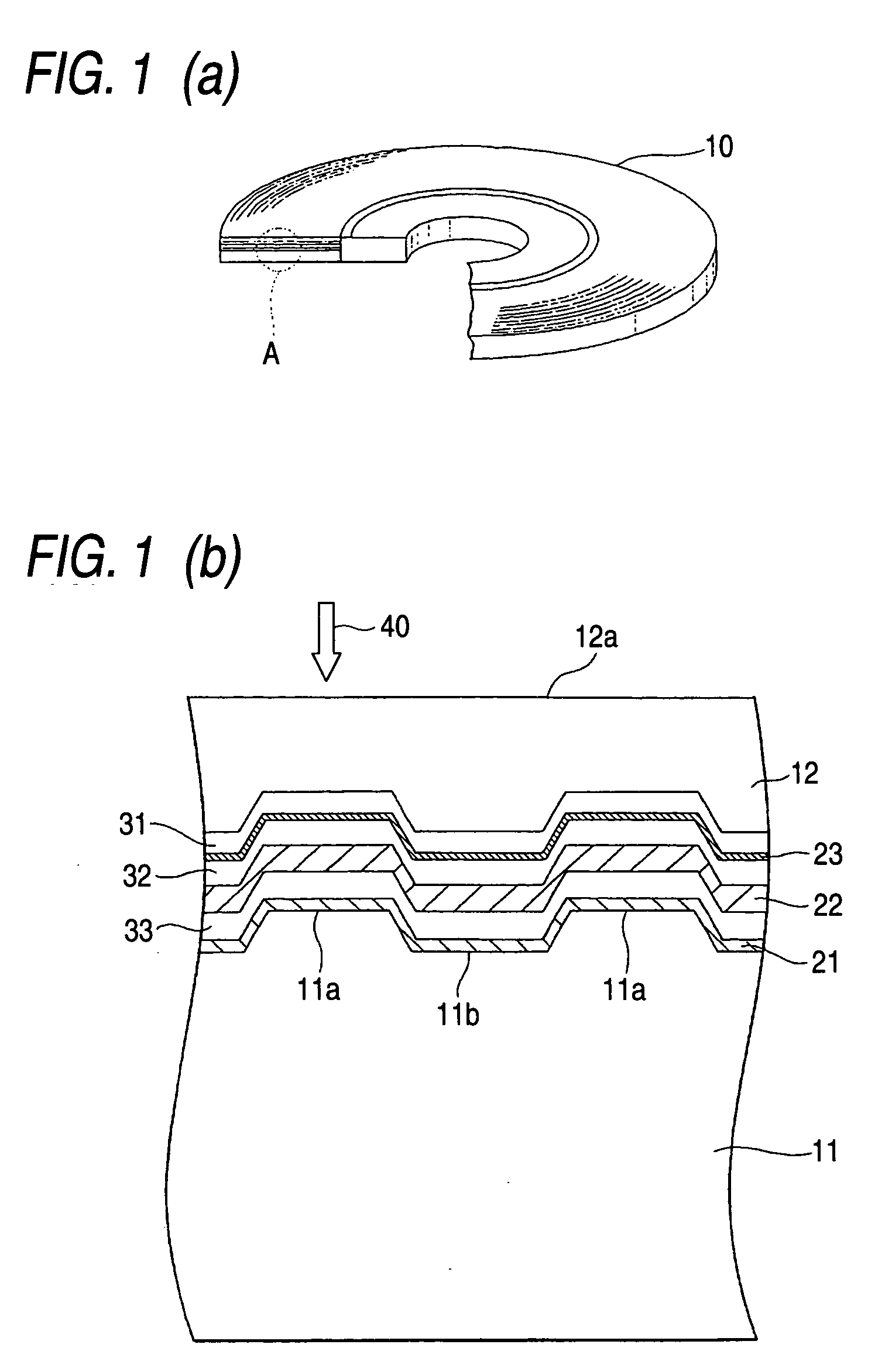
[0107] First, the disc-shaped support substrate 11, which has a thickness of about 1.1 mm, a diameter of about 120 mm, and the grooves 11a and the lands 11b formed in a front face of the substrate, was formed from polycarbonate by means of injection molding.

[0108] Next, the support substrate 11 was set in a sputtering system. In the side of the support substrate where the groove 11a and the land 11b are formed, there were sequentially formed the reflection layer 21 which is formed essentially from platinum (Pt) and has a thickness of about 20 nm; the dielectric layer 33 which is formed essentially from a mixture consisting of ZnS and SiO2 (a mol ratio of about 80:20) and has a thickness of about 80 nm; the light absorption layer 22 which is formed essentially from AgaInbSbcTed (a=5.9, b=4.4, c=61.1, d=28.6) and has ...

second embodiment

[0111] The thickness of the dielectric layer 33 was set to about 100 nm, and the thickness of the noble metal nitride layer 23 was set to about 4 nm. In other respects, an optical recording medium sample of a second embodiment was produced in the same manner as was the optical recording medium sample of the first embodiment.

[0112] [First Evaluation of Characteristic]

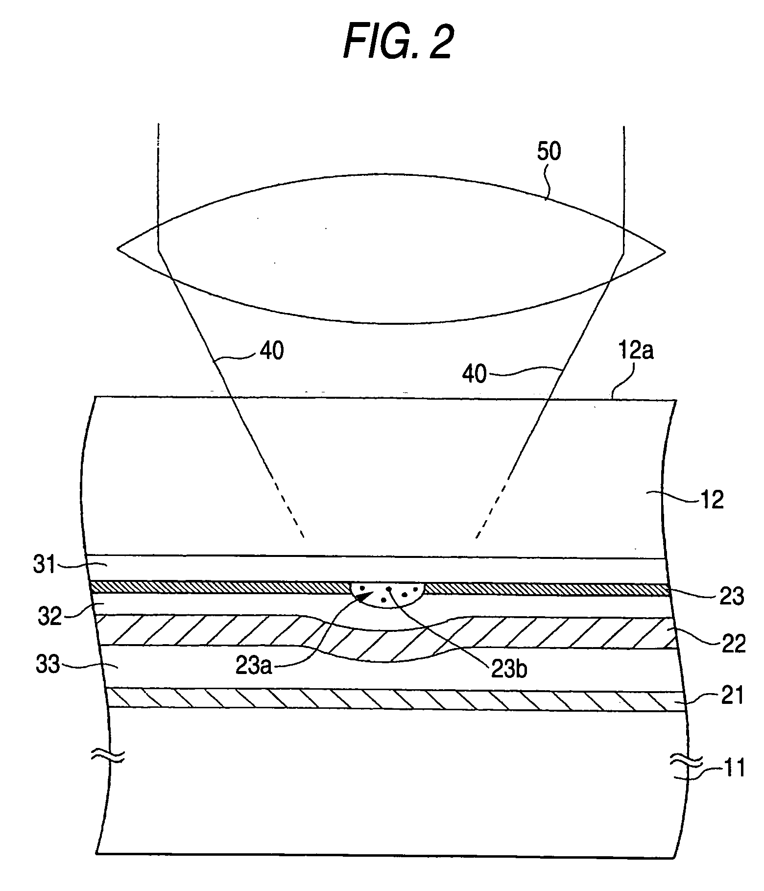
[0113] First, the optical recording medium sample of the first embodiment and that of the second embodiment were set in an optical disk evaluation system (DDU1000 manufactured by Pulstec Industrial Co., Ltd.). While the optical recording medium was being rotated at a linear velocity of about 6.0 m / s, a laser beam having a wavelength of about 405 nm was irradiated onto the noble metal nitride layers 23 from the light entrance faces 12a by way of an objective lens having a numerical aperture of about 0.85, to thus record a single frequency signal having a predetermined record mark length and a blank length. The record mar...


PUM

PropertyMeasurementUnit
thicknessaaaaaaaaaa
thicknessaaaaaaaaaa
thicknessaaaaaaaaaa

Abstract

An optical recording medium 10 of the present invention has a support substrate 11 and a light-transmitting layer 12, and further has a first dielectric layer 31, a noble metal nitride layer 23, a second dielectric layer 32, a light absorption layer 22, a third dielectric layer 33, and a reflection layer 21, all of which are interposed between the light-transmitting layer 12 and the support substrate 11. In the optical recording medium of the present invention, a laser beam 40 is irradiated on the substrate from the light entrance face 12a, to thus locally decompose the noble metal nitride layer 23, so that record marks can be formed by means of resultant bubble pits. In this case, a gas filling the bubble pits, which are to form the record marks, is a chemically-stable nitrogen gas (N2). The risk of this gas oxidizing or corroding other layers is very remote, and high storage reliability can be achieved.

Description

FIELD OF THE INVENTION [0001] The present invention relates to an optical recording medium and a method for manufacturing the optical recording medium, and more particularly, to an optical recording medium of a type in which record marks are formed by means of generation of a gas, as well as to a method for manufacturing the recording medium. Moreover, the present invention relates to a method for recording and reproducing data on and from an optical recording medium, as well as to a method for recording and reproducing data on and from an optical recording medium of a type in which record marks are formed by generation of a gas. BACKGROUND [0002] In recent years, optical recording mediums typified by a CD (Compact Disc) and a DVD (Digital Versatile Disc) have been widely used as recording mediums used for recording a large volume of digital data. [0003] Among CDs, a CD of a type (CD-ROM) that does not allow additional writing or rewriting of data has a structure where a reflection ...

Claims


Application Information

Patent Timeline
Patent Type & Authority Applications(United States)
IPC IPC(8): G11B7/24B41M5/26G11B7/0045G11B7/005G11B7/24035G11B7/24056G11B7/24067G11B7/243G11B7/2433G11B7/2542G11B7/26
CPCG11B7/00452G11B2007/25716G11B7/2531G11B7/2533G11B7/2534G11B7/2536G11B7/2542G11B7/26G11B2007/24306G11B2007/24308G11B2007/24322G11B2007/25706G11B2007/2571G11B2007/25715G11B7/252G11B7/241G11B7/257G11B7/0045
Inventor FUKUZAWA, NARUTOSHIKIKUKAWA, TAKASHIKOBAYASHI, TATSUHIRO
Owner TDK CORPARATION
Why Eureka
Try Eureka