Vibration system part for speaker device and manufacturing method thereof

Inactive Publication Date: 2006-11-09
PIONEER CORP +1
View PDF13 Cites 23 Cited by
  • Summary
  • Abstract
  • Description
  • Claims
  • Application Information

AI Technical Summary

Benefits of technology

[0013] The present invention has been achieved in order to solve the above problems. It is an object of this invention to provide a vibration

Problems solved by technology

Though the carbon fiber is excellent in its light weight and high rigidity, it is expensive.
Though the ceramic fiber is excellent in its high rigidity, it is problematically expensive.
Further, it is problematic that the ceramic fiber is easily broken at the time of processing.
Though ultra-high strength fiber such as the aramid fiber and the PBO fiber is excellent in its light

Method used


Image

  • Vibration system part for speaker device and manufacturing method thereof
  • Vibration system part for speaker device and manufacturing method thereof
  • Vibration system part for speaker device and manufacturing method thereof

Examples


Embodiment Construction

[0031] The preferred embodiments of the present invention will now be described below with reference to the attached drawings. [0032] [Configuration of Vibration System Parts for Speaker Device]

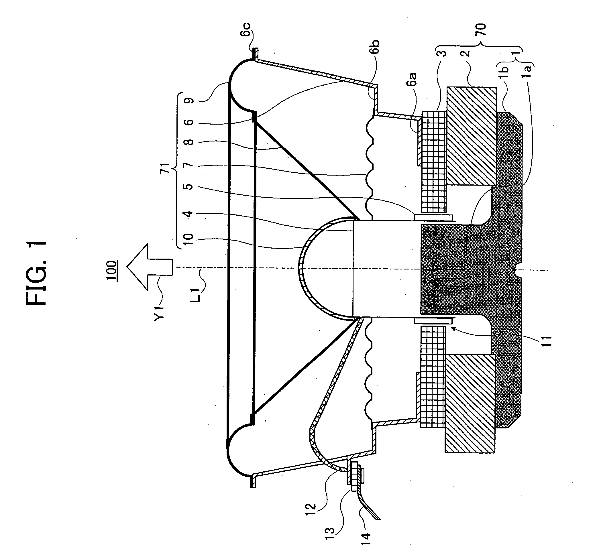
[0033]FIG. 1 shows a cross-sectional view of a speaker device 100 including the vibration system parts for the speaker device of the present invention when cut by a plane including a central axis L1.

[0034] As shown in FIG. 1, the speaker device 100 mainly includes a magnetic circuit 70 having a yoke 1, a magnet 2 and a plate 3, and a vibration system 71 (hereinafter, also referred to as “vibration system parts for a speaker device”) having a voice coil bobbin 4, a voice coil 5, a frame 6, a damper 7, a diaphragm 8, an edge 9 and a center cap 10. In the present invention, a configuration and a driving system of the speaker device, shapes, positions and sizes of the vibration system parts for the speaker device are not limited to configurations which will be described below.

[0035] First, a co...


PUM


Abstract

A Vibration system part for a speaker device includes a woven fabric or a non-woven fabric made of basalt fiber produced by twist yarn or roving yarn being a continuous long-fiber. The vibration system part for the speaker device may be a diaphragm, a center cap, an edge or a damper, for example. In a preferred example, the woven fabric or the non-woven fabric is impregnated with thermosetting resin or thermoplastic resin. Additionally, a lamination member, such as paper, foam material, resin or a film, is preferably laminated (coated) on the woven fabric or the non-woven fabric. Thus, the vibration system parts for the speaker device, having excellent acoustic property and reliability, can be obtained at a low price.

Description

BACKGROUND OF THE INVENTION [0001] 1. Field of the Invention [0002] The present invention relates to a component material of vibration system part for a speaker device. [0003] 2. Description of Related Art [0004] Conventionally, as a fabric material of a diaphragm being a vibration system part for a speaker device, there is normally used a woven fabric or a non-woven fabric of inorganic fiber such as carbon fiber, glass fiber and ceramic fiber and an organic fiber such as aramid fiber and a PBO fiber (polypara phenylene benzobis imidazole fiber). [0005] In addition, the fabric material of the above-mentioned fiber is generally used in such a state that the fabric material is impregnated with a thermosetting resin and then hardened by hot press. Additionally, the above fabric material of the fiber is sometimes used in such a state that a material, such as paper, foam and thermoplastic resin, is laminated on the surface thereof. [0006] The fabric material to which such process is appl...

Claims


Application Information

Patent Timeline
IPC IPC(8): H04R7/00
CPCH04R7/122H04R31/003H04R2307/029H04R2307/025H04R2307/023
Inventor SATO, MASATOSHIHACHIYA, SATOSHIKOBAYASHI, HIROYUKITAKAYAMA, KOJI
Owner PIONEER CORP
Why Eureka
Try Eureka