[0027] A related, more specific object of the invention is to provide a RFID tag of extremely compact size and thinness, in the form of a sticker to be adhesively applied to an object whose identity, features, characteristics, authorized use or other aspects are discernible from data stored in tag memory accessible by a RFID reader, and which is adapted to communicate with the reader through a
tag antenna of small aperture design, such as a
slot antenna, and of polygonal shape with central aperture.
[0028] Other objects include increasing efficiency of antenna and matching elements of the RFID tag to reduce incident RF power requirements and increase operational range of the tag; obtaining wider bandwidth operation of the tag, by some 10% to 20% over current bandwidths; enabling self-adhesion of the tag in highly
compact form to the
windshield or other surface of a roadway or railway vehicle, with electrical components of the tag designed and positioned for optimum performance of the tag in communication sessions with a RFID reader; incorporating low-cost
DC block at the
antenna feed terminals to be compatible with a
voltage-doubler constructed with Schottky diodes whether external or internal to an
integrated circuit (IC)
chip of the tag; reducing variability of performance of the tag when mounted on objects with different electrical properties; and rendering the tag capable of use in extremes of vibration, chemicals, dust, temperature and
humidity and other adverse atmospheric or ambient conditions.
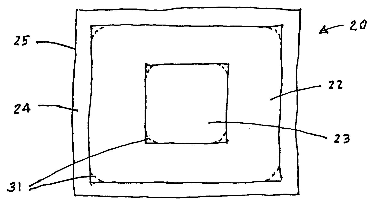
[0030] According to the most preferred embodiment of the invention, a RFID tag includes a flat, or planar, structure (i.e., relatively smooth with its major surfaces essentially parallel and distinctly greater than its minor surfaces) for
adhesive application to the surface of an object to identify the object or a characteristic or feature thereof from data stored in the tag accessible by a RFID reader. The flat structure may be a sticker that incorporates a small aperture antenna, such as a
slot antenna, in the form of a polygon having
electrically conductive sides. The polygon may be square, rectangular, or in the limit of multiple sides, circular or elliptical, or some other polygonal figure. A central open portion within the polygon constitutes the aperture of the antenna. An
integrated circuit chip containing the
electronics of the tag is secured to the flat structure within the boundary of the aperture, substantially
equidistant from a pair of opposite sides of the polygon, with a pair of conductive impedance matching elements of substantially equal length extending toward each other into the aperture from those opposite sides for minimizing losses in communication between antenna and chip.
[0041] Preferably, the flat structure of the tag and its components are encompassed within a
coating, such as a lamination, for protection against damage from ambient environment, and also, with an
adhesive side exposed to allow the sticker to be adhesively applied to the object of interest.
[0042] The RFID tag is preferably but not necessarily of the passive type. The small aperture antenna is of a size considerably smaller than a half
wavelength of the nominal RF frequency at which the tag is to operate. The antenna's small size and the impedance matching circuit's relatively large
shunt impedance (which is considered practically an open circuit with very
high impedance, i.e., on the order of 1500 ohms) and relatively small
series impedance are significant factors in enabling the RFID tag of the invention to be fabricated in the form of a very thin, extremely compact sticker. Thus, the tag is suitable for self-adhesion to the
windshield or other
structural component of a vehicle for use in moderate to high speed applications, such as on-the-fly highway
toll collection systems and moving rail car asset identification systems. Examples of use of the RFID tag of the invention in other vehicle applications include access to parking spaces in gated parking facilities, electronic vehicle registration stickers, in gated secure facilities and in any application where remote identification of a vehicle is required.
[0045] Another aspect of the invention resides in a method of enabling a vehicle to be detected automatically as being authorized for passage through a restricted lane equipped with a RFID reader, including the step of making available to the vehicle a RFID tag in the form of a planar compact sticker that incorporates a storage medium programmed with
authorization data that identifies the vehicle as being permitted to pass through the restricted lane without stopping. The sticker includes a small aperture antenna implemented as a polygon with central aperture for optimized communication of the stored
authorization data from the antenna in a
backscatter RF
signal in response to an interrogating RF signal from the RFID reader within
RF communication range of the tag.

