Method and arrangement for local sychronization in master-slave distributed communication systems

a distributed communication system and master-slave technology, applied in data switching networks, time-division multiplexing selection, multiplex communication, etc., can solve the problems of requiring some complexity overhead, is not easy to achieve, and is generally more complex and less efficient than single-stage switches. achieve maximum throughput, ample time, and high bandwidth

Inactive Publication Date: 2006-11-09
IBM CORP
View PDF15 Cites 25 Cited by
  • Summary
  • Abstract
  • Description
  • Claims
  • Application Information

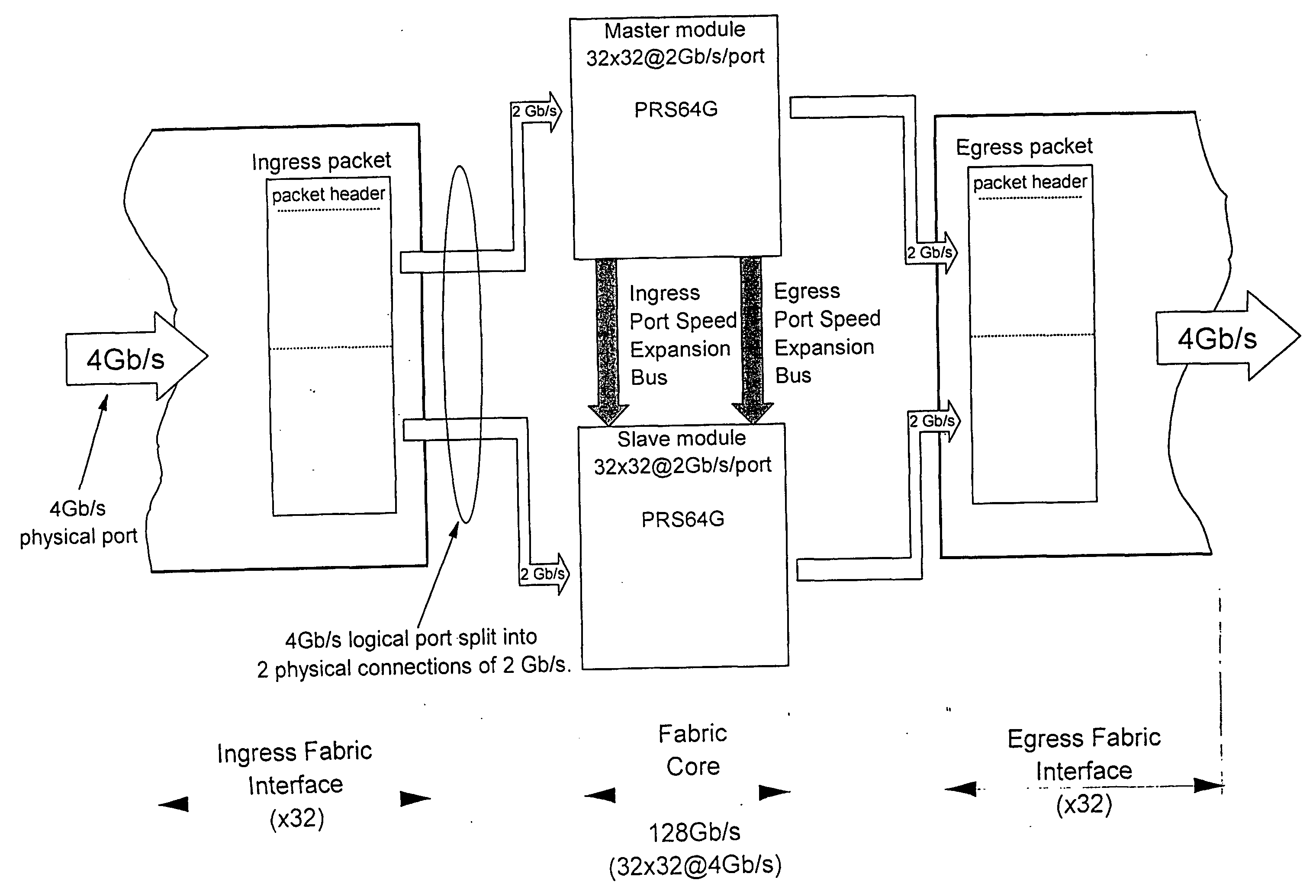
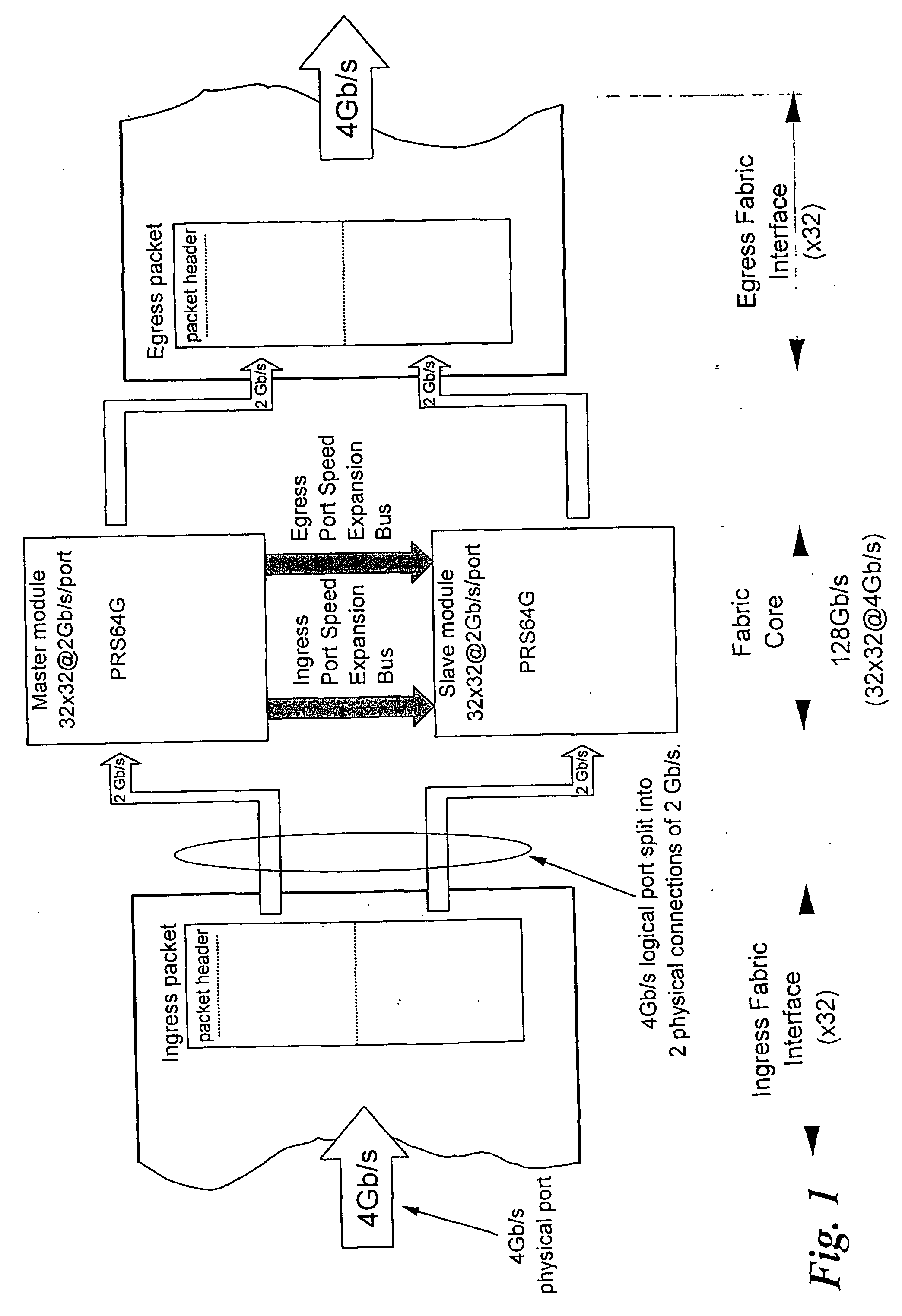
AI Technical Summary

Benefits of technology

[0006] In the computer community, data and pipeline parallelism have long been exploited to achieve higher bandwidth. When applied to packet switching technology in electronic networks, this translates into packets being switched over multiple parallel slices, and is sometimes referred to as Port Speed Expansion.
[0007] An early description of port speed expansion can be found in an article by W. E. Denzel, A. P. J. Engbersen, and I. Iliadis, entitled “A flexible shared-buffer switch for ATM at Gb / s rates”, published in Computer Networks and ISDN Systems, Vol. 27, No. 4, Jan. 1995, pp. 611-624. In this paper, port speed expansion is used to expand the port rate in a modular fashion by stacking multiple slaves chips and have them controlled by a single-master chip.
[0008] A particular port speed expansion embodiment applied to an output queued switch architecture is also described in the European patent application EP0849917A2.
[0009] The problem concerned with the present invention is now in more detail the following. A well known difficulty of port speed expansion is the complexity of its implementation due to the fact that master and slave modules have to be tightly synchronized. At high port rate, this leads to complex and / or expensive synchronization logic which usually limits the physical degree of parallelism and thus the maximally achievable throughput. Therefore there is a need to decouple the scalability of a port speed expansion scheme from its implementation complexity incurred by synchronization issues.
[0010] In a switch fabric core operated in port speed expansion mode, the component switches are termed as either “Master” or “Slave” switch. A port speed expanded switch fabric contains one Master, and one or more Slaves components. Master and Slaves may be connected in any arbitrary topology such as a chain, a ring, or a tree. The general concept of port speed expansion is now described / recalled with reference to FIG. 1 which illustrates an example related to the prior art commercial product IBM PRS64G where only one Slave is used. The PRS64G is a packet routing switch that implements 32 input and 32 output ports, each running at 2 Gb / s, for a total aggregate bandwidth of 64 Gb / s. Combining two of these chips in port speed expansion mode enables to operate the physical ports at 4 Gb / s and to build a switch fabric with twice the aggregate bandwidth (128 Gb / s). When a packet to be switched is received by the ingress fabric interface it is split into several parts, termed here “Logical Unit” (LU) (or later also termed “Segment”). In this particular example, the number of LU's equals the number of component switches, but this is not a prerequisite. Next, the ingress fabric interface sends one LU of each packet to the Master switch, and the following LU to the Slave switch. The first LU contains only part of the initial packet payload but it has the full packet header which includes handling information. The second LU, which is passed to the Slave, contains only payload information and no routing information. The Master handles its LU according to the routing and Quality-of-Service information carried by the packet header, and then informs the Slave about its scheduling decision by sending an appropriate (derived) control information to it. For every LU received by the Master, a derived control information is sent to the Slave over a so-called ingress port speed expansion bus. Likewise, when the Master schedules a packet to be transmitted, a similar control information is sent to the Slave over an egress port speed expansion bus. Because of the propagation delay of the egress control path, the master egress LU may actually leave earlier than the slave egress LU. In some cases, an additional transmit synchronization mechanism may be needed between the Master and the Slave, if the two outgoing LU's are required to reach the egress fabric interface at nearly the same time. From the description above, it is obvious that a port speed expanded fabric calls for control of the propagation delays and a precise match of two different flows, namely: the data flow from ingress fabric interface toward fabric core and egress fabric interface (drawn horizontally in FIG. 1) and the control flow from master to one or multiple Slaves (drawn vertically in FIG. 1). Given the packet duration example of FIG. 1 (128 ns for a 64 Bytes packet) and the compactness of the switch fabric core (built on a single-board), this was easily achieved by ensuring that the control information reaches the Slave within one packet cycle of 128 ns, which is ample of time for a single board design in the current technology.
[0011] Meanwhile, because of continuous increase in data link rates and system sizes, speed expanded systems have gotten progressively more and more difficult to build. On one side, the faster data link rates have caused packet durations to decrease but have required higher degree of parallelism in the port speed expansion implementations. On the other side, bigger system sizes have forced designers to distribute the switch fabric over multiple boards and racks, thus increasing link distances for data flows and / or control flows within the fabric. Given all these more strict system requirements and sizes, it gets very difficult and / or expensive to precisely control and match the propagation delays between elements which are physically distributed and for which packet durations have decreased at the same time. In particular, it may occur that the multiple LU's from one packet may not arrive at the Master and one or more Slave switches at the same or close to the same time. In fact, it may occur that LU's from completely different packets arrive at the Master and / or the Slave switches at the same or nearly the same time.

Problems solved by technology

The second option is the multistage switch architecture which provides higher throughput by means of more parallelism, but which is generally more complex and less efficient than single stage switches.
Its main drawback is that it requires some complexity overhead incurred by load balancing and reordering algorithms that handle the packets distributed over the multiple switch domains.

Method used


Image

  • Method and arrangement for local sychronization in master-slave distributed communication systems
  • Method and arrangement for local sychronization in master-slave distributed communication systems
  • Method and arrangement for local sychronization in master-slave distributed communication systems

Examples


Embodiment Construction

[0036] With general reference to the figures and with special reference now to FIG. 3, a general communication system 30 that transports data entities, hereafter called packets, is considered. Beyond certain stringent requirements of size or performance, parallelism is sometimes the only feasible solution in any given technology.

[0037] Parallelism can be achieved by partitioning and distribution of the system. The combined functionality of the distributed parts 30-1 to 30-N, is identical to the functionality of the original system 30. Therefore a packet 31 is also partitioned (into segments) and transported through the communication system by processing different parts of the packet in different parts of the system. Partitioning of the system and the packet is depicted in the lower part of FIG. 3. A typical example of such a parallel system is the case where M=N and each segment of a packet is processed by a corresponding part of the communication system.

[0038] Segmentation of the...


PUM


Abstract

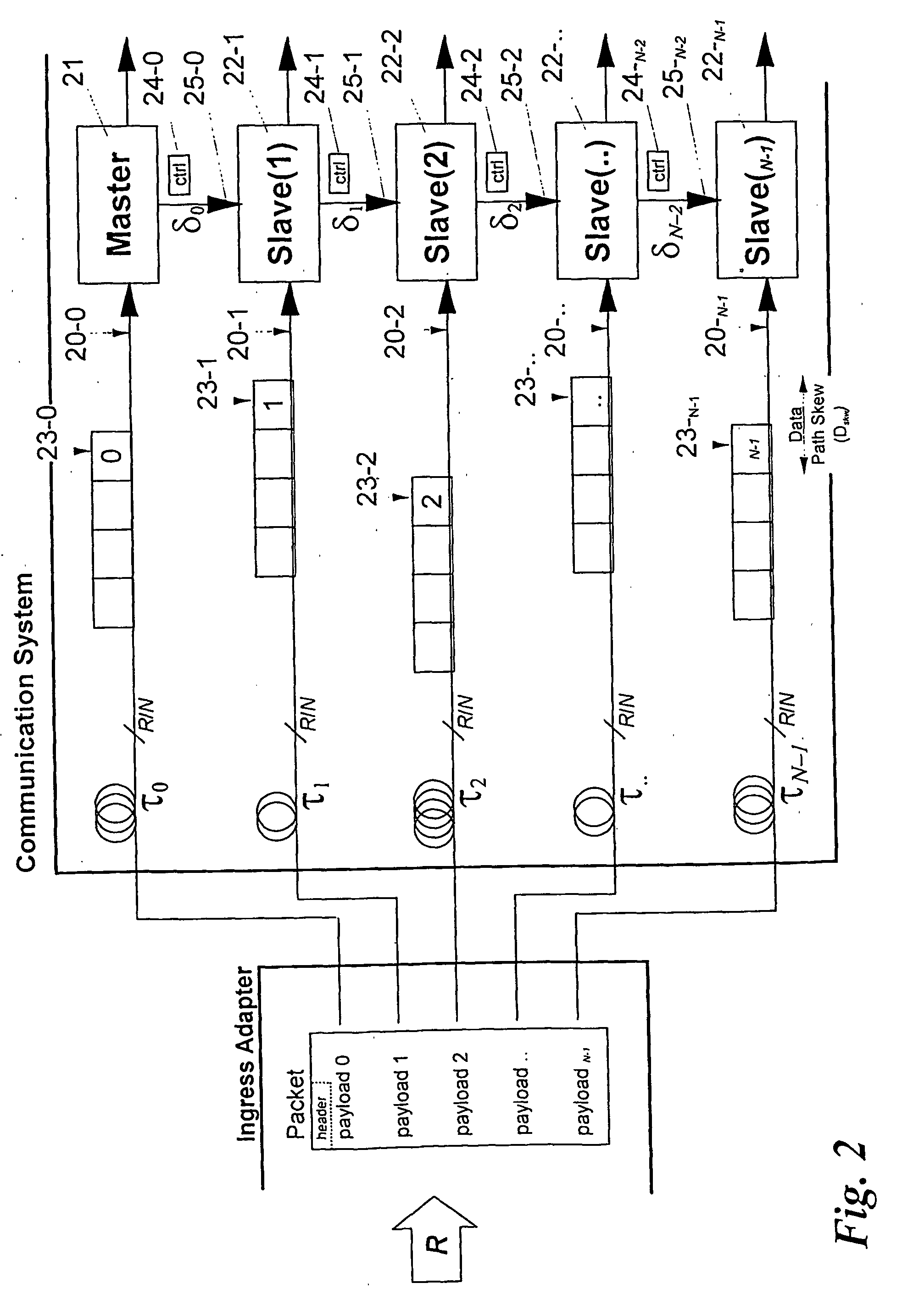
For switching or transmitting data packets, one can provide communication systems which consist of several modules—operating in parallel on segments of a packet—to increase speed and handling capacity. One module acts as master (21), the others are slave modules (22) controlled by control signals (25) derived by the master module. It is important that in each module the data segment and the respective control signal of each packet are correctly synchronized, because in large systems the data paths carrying packet segments and the control signal paths may have substantially different delays. The invention provides for measurement of the propagation delay differences and for introducing a controlled delay in each slave module, so that data segments and control signals can be correctly correlated by delaying either the one or the other. Synchronization packets are transmitted besides normal data packets, for obtaining time stamps which are used to determine the delay difference.

Description

FIELD OF THE INVENTION [0001] The present invention relates to packet handling technology in electronic communication networks and the design structure of the processing arrangements used therefor. More particularly it refers to a method and apparatus for synchronizing multiple processing elements (or modules) operated in parallel, to form the equivalent of a single processing arrangement with aggregate throughput equal to the sum of the combined aggregate throughput of multiple parallel processing elements. A typical application of this invention is in packet switching systems. INTRODUCTION [0002] Among all the competing requirements put on the switch fabric designs of the current generation, scalability of number of ports and cost-effectiveness are two fundamental issues that should be addressed. Two ways to build a cost-effective and scalable switch fabric are distinguish. The first option is the widely adopted single-stage switch architecture which is very efficient but has scal...

Claims


Application Information

Patent Timeline
Patent Type & Authority Applications(United States)
IPC IPC(8): H04J3/06H04L12/56H04Q11/04
CPCH04L49/153H04L49/254H04L49/45H04L49/3072H04L49/3081H04L49/3009
Inventor COLMANT, MICHELBENNER, ALANABEL, FRANCOIS G.PORET, MICHELSCHUMACHER, NORHERTBLANC, ALAINVERHAPPEN, MARKGUSAT, MITCH
Owner IBM CORP
Why Eureka
Try Eureka