Vehicle suspension assembly

a technology for suspension assemblies and vehicles, applied in resilient suspensions, vehicle springs, interconnection systems, etc., to achieve the effect of reducing the weight of the assembly, preventing the potential relaxation of compression loads in the joint between the extension member and the beam, and increasing the roll and lateral shift resistan

Active Publication Date: 2006-11-16
THE HOLLAND GROUP
View PDF20 Cites 26 Cited by
  • Summary
  • Abstract
  • Description
  • Claims
  • Application Information

AI Technical Summary

Benefits of technology

[0009] The present inventive vehicle suspension assembly maintains the ride-cushioning characteristics of an air spring suspension system, while simultaneously increasing roll and lateral shift resistance. The weight of the assembly is minimized by allowing the use of different materials to construct a single trailing arm or beam. Further, relatively longer and smaller diameter bolts are utilized that are allowed to “stretch” during assembly, thereby compensating for wear on components that may create gaps in the suspension assembly during use. Moreover, by interference-fitting the extension member into the main beam, within a separate component that is then welded to the main beam, potential relaxing of compression loads in the joint between the extension member and the beam is prevented.
[0010] The addition of a pocket or passage that can secure a nut on the bottom side of the main beam aids in assembly as suspension assemblies are typically constructed upside down, and further eliminates the need for a wrench to secure the fastener by frictionally securing a plurality of sides of a fastener. Further, the downward opening orientation of the passage facilitates the drainage of water, snow, and debris from the pocket during normal operating conditions, thus reducing the potential for corrosion. Moreover, the present inventive vehicle suspension assembly is efficient to make and use, economical to manufacture and repair, capable of a long operating life, and particularly well-adapted for the proposed use.

Problems solved by technology

Further, relatively longer and smaller diameter bolts are utilized that are allowed to “stretch” during assembly, thereby compensating for wear on components that may create gaps in the suspension assembly during use.

Method used


Image

  • Vehicle suspension assembly
  • Vehicle suspension assembly
  • Vehicle suspension assembly

Examples


Embodiment Construction

[0022] For purpose of description herein the terms “upper”, “lower”, “right”, “left”, “rear”, “front”, “vertical”, “horizontal” and derivatives thereof shall relate to the invention as oriented in FIGS. 1 and 4. However, it is to be understood that the invention may assume various alternative orientations and step sequences, except where expressly specified to the contrary. It is also to be understood that the specific devices and processes illustrated in the attached drawings, and described in the following specification are exemplary embodiments of the inventive concepts defined in the appended claims. Hence, specific dimensions and other physical characteristics relating to the embodiments disclosed herein are not to be considered as limiting, unless the claims expressly state otherwise.

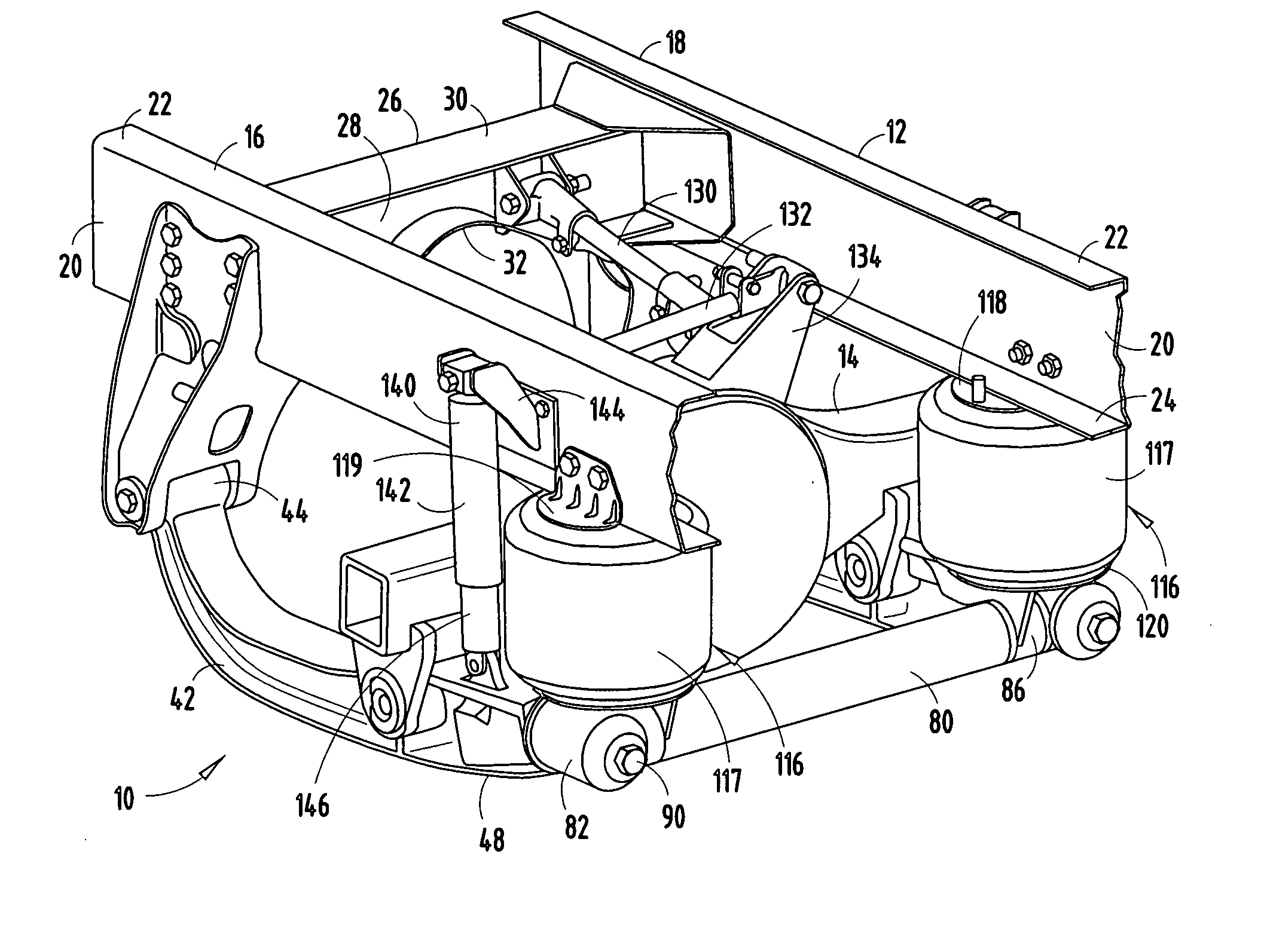
[0023] The reference numeral 10 (FIGS. 1A and 1B) generally designates a vehicle suspension assembly embodying the present invention, and supporting a vehicle frame 12 above a vehicle axle 14 and...


PUM


Abstract

A vehicle suspension assembly that includes first and second main beams each having a first end operably coupled to a vehicle frame, and a second end having a cavity formed therein, and first and second extension members each having an aperture extending therethrough, wherein the first and second extensions are interference-fit within and extend outwardly from the cavity of the first and second main beams, respectively. The assembly further including a torsion member having apertured first and second ends that receive the first and second extension members therein, and threaded mechanical fasteners extending through the apertures of the first and second extension members and engage nuts that are frictionally engaged by the first and second main beams.

Description

CROSS REFERENCE TO RELATED APPLICATION [0001] This application claims the benefit of U.S. Provisional Application No. 60 / 680,558, filed May 13, 2005, entitled VEHICLE SUSPENSION ASSEMBLY, which is hereby incorporated herein by reference in its entirety.BACKGROUND OF THE PRESENT INVENTION [0002] The present invention relates to a vehicle suspension assembly, and in particular to a heavy-duty suspension system with increased load capacity and decreased weight. [0003] Various suspension systems utilizing air springs have been developed for semi-tractor trailers and other heavy vehicles. These systems are typically designed to control the position of the chassis relative to an associated axle and to cushion any movement of the axle with respect to the chassis frame. Although these systems provide excellent chassis control over a wide range of loading conditions, conventional air spring systems typically do not offer acceptable resistance to vehicle roll, as is often experienced when the...

Claims


Application Information

Patent Timeline
Patent Type & Authority Applications(United States)
IPC IPC(8): B60G9/00B60G11/20
CPCB60G7/001B60G9/003B60G11/27B60G2200/31B60G2206/8207B60G2206/011B60G2206/012B60G2206/11B60G2206/201B60G2202/152
Inventor HASS, TAVEJOHNSON, MARC R.MOLITOR, MARK R.CONAWAY, RICHARD L.
Owner THE HOLLAND GROUP
Why Eureka
Try Eureka