LED drive circuit, LED lighting device, and backlight

Active Publication Date: 2006-11-16
SHARP KK
View PDF3 Cites 102 Cited by
  • Summary
  • Abstract
  • Description
  • Claims
  • Application Information

AI Technical Summary

Benefits of technology

[0017] Accordingly, the LED circuits carry equal currents even if the first and second LED circuits vary in the forward current-forward voltage characteristics. The arrangement thus addresses variations in light intensity (luminance level) between the LED circuits. The arrangem

Problems solved by technology

These defects can cause problems when the device is applied for illumination purposes and to the area light source in the backlight for large-scale liquid crystal displays.
Variations in emitted light intensity can be a cause for uneven luminance.
Different current values

Method used


Image

  • LED drive circuit, LED lighting device, and backlight
  • LED drive circuit, LED lighting device, and backlight
  • LED drive circuit, LED lighting device, and backlight

Examples


embodiment 1

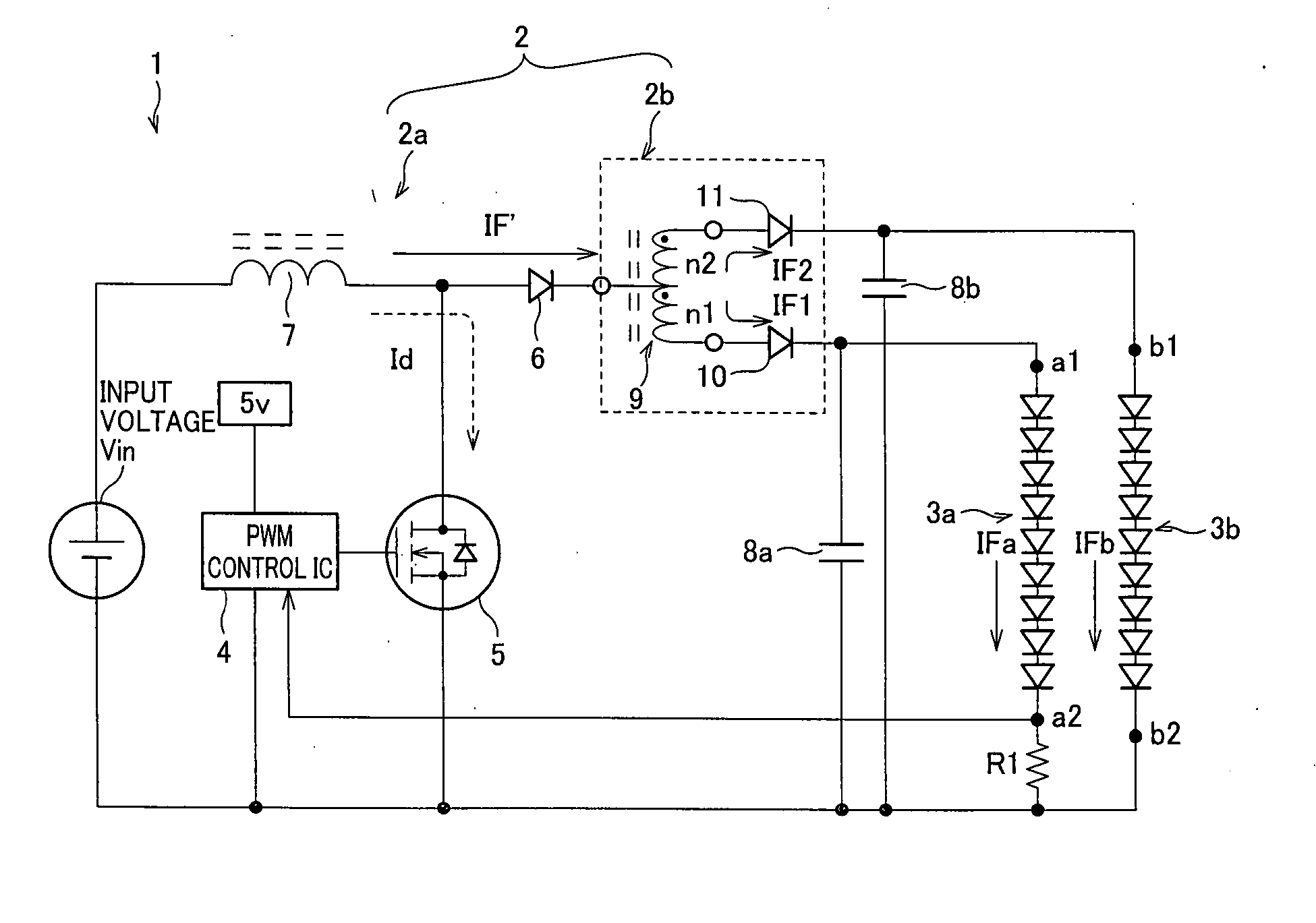
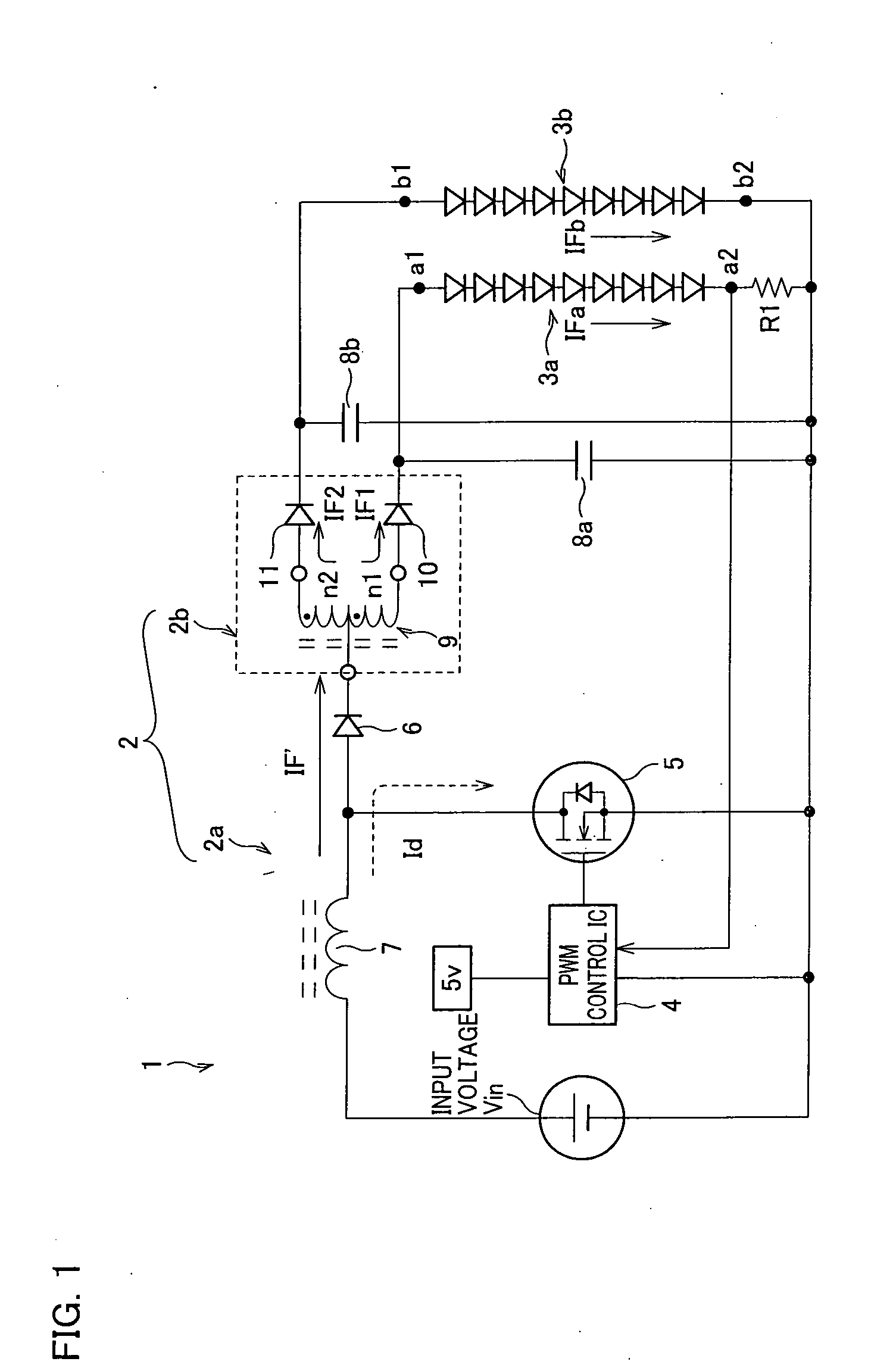
[0030] The following will describe an embodiment of the LED drive circuit of the present invention. FIG. 1 is a circuit diagram illustrating the arrangement of an LED lighting device for embodiment 1.

[0031] As shown in the figure, the LED lighting device 1 contains an input power supply Vin, an LED drive circuit 2, and two LED circuits 3a and 3b. The LED drive circuit 2 contains a switchable power supply circuit 2a and a current-dividing circuit 2b. The switchable power supply circuit 2a, connected to the input power supply Vin, contains a PWM control IC 4, a switching element 5 (N-channel MOS transistor), a diode 6, a coil 7, smoothing capacitors 8a and 8b, and a resistor R1. The current-dividing circuit 2b contains a current-dividing coil (inductor) 9 and diodes (reverse current blocking diodes) 10 and 11. The current-dividing coil 9 is made up of a winding n1 of n1 turns and a winding n2 of n2 turns, both wound around the same core, which are coupled together at a center tap (re...

embodiment 2

[0041] The following will describe another embodiment of the LED drive circuit of the present invention. FIG. 4 is a circuit diagram illustrating the arrangement of an LED lighting device for embodiment 2.

[0042] As shown in the figure, the LED lighting device 101 contains an input power supply Vin, an LED drive circuit 102, and four LED circuits 103a to 103d. The LED drive circuit 102 contains a switchable power supply circuit 102a and a current-dividing circuit 102b. The switchable power supply circuit 102a, connected to the input power supply Vin, contains a PWM control IC 104, a switching element 105, a diode 106, a coil 107, smoothing capacitors 108a to 108d, and a resistor R2. The current-dividing circuit 102b contains current-dividing coils 109x to 109z and diodes 110 to 113 (reverse current blocking diodes). The current-dividing coils 109x to 109z are each made up of two windings wound around the same core which are coupled together at a center tap. The LED circuit 103a is m...

embodiment 3

[0049] The following will describe another embodiment of the LED drive circuit of the present invention. FIG. 6 is a circuit diagram illustrating the arrangement of an LED lighting device for embodiment 3.

[0050] As shown in the figure, the LED lighting device 201 contains an AC power supply, an LED drive circuit 202, and four LED circuits 203a to 203d. The LED drive circuit 202 contains a switchable power supply circuit 202a and a current-dividing circuit 202b. The switchable power supply circuit 202a, connected to the AC power supply, contains bridged diodes 220, a capacitor 221, resistors Ra and Rb, a PWM control IC 204, a switching element 205 (N-channel MOS transistor), a coil 207 (with a core), smoothing capacitors 208a to 208d, a photocoupler 255 (for both emission and receipt of light), and resistors R3 and R4. The current-dividing circuit 202b contains current-dividing coils 209x to 209z and diodes 210 to 213 (reverse current blocking diodes). The current-dividing coils 209...


PUM


Abstract

To realize an LED drive circuit capable of feeding equal currents to parallel-connected LED circuits with a simple arrangement, there are provided a current source generating a temporally altering current and a first smoothing capacitor and a second smoothing capacitor, and there are also provided: a first LED circuit, containing one LED or series-connected LEDs, which is connected in parallel with the first smoothing capacitor; and a second LED circuit, containing one LED or series-connected LEDs, which is connected in parallel with the second smoothing capacitor, the drive circuit comprising: a current-dividing coil containing two coils coupled at a tap so that the current generated in the current source flows into the tap; a first reverse current blocking diode connected between an end of the current-dividing coil and an electrode of the first smoothing capacitor; and a second reverse current blocking diode connected between another end of the current-dividing coil and an electrode of the second smoothing capacitor.

Description

[0001] This nonprovisional application claims priority under 35 U.S.C. § 119(a) on Patent Application No. 141906 / 2005 filed in Japan on May 13, 2005, the entire contents of which are hereby incorporated by reference. FIELD OF THE INVENTION [0002] The present invention relates in general to an LED (light emitting diode) lighting device, for example, those used in the backlight of liquid crystal displays, and in particular to a drive (switch-on) circuit (LED drive circuit) for such a device. BACKGROUND OF THE INVENTION [0003]FIG. 9 is a circuit diagram for a conventional LED lighting device. As shown in the figure, the LED lighting device 801 includes an input power supply Vin (DC power supply), an LED drive circuit, and four LED circuits (803a to 803d). The LED drive circuit includes a PWM control IC 804, a switching element 805, a diode 806, a coil 807, resistors Ra to Rd, and a smoothing capacitor 808. The LED circuit 803a is made up of 10 LEDs connected in series between a node a1...

Claims


Application Information

Patent Timeline
IPC IPC(8): H05B39/00H01L33/00H05B37/02
CPCH05B33/0815Y02B20/347H05B33/0851H05B45/10H05B45/35Y02B20/30H05B45/18H05B45/38
Inventor SAWADA, SHINICHISHIMIZU, TAKAYUKI
Owner SHARP KK
Why Eureka
Try Eureka