Device and method for correcting a path trouble in a communication network

a path trouble and communication network technology, applied in data switching networks, frequency-division multiplexes, instruments, etc., can solve problems such as failure recovery failure, network operations may be hindered, and it is difficult to realize high-quality communication services. , to achieve the effect of reducing the disconnection of a normal path set, reducing the difficulty of failure recovery, and reliable failure recovery

Inactive Publication Date: 2006-11-16
NIPPON TELEGRAPH & TELEPHONE CORP
View PDF14 Cites 97 Cited by
  • Summary
  • Abstract
  • Description
  • Claims
  • Application Information

AI Technical Summary

Benefits of technology

[0022] A second object of the present invention is to provide, in a large capacity communication network autonomously controlled in a distributed way, a backup path bandwidth keeping method and a path switching apparatus that can dynamically keep a number of channels necessary for a channel group that accommodates backup paths so as to realize reliable failure recovery for a single link failure, and that can also flexibly support multiple link failure.
[0023] A third object of the present invention is to provide, in a large capacity communication network that is autonomously controlled in a distributed way and that is virtually set on a link, a backup path bandwidth keeping method and a path switching apparatus that can dynamically keep a number of channels necessary for a channel group that accommod

Problems solved by technology

When a failure occurs, there is a possibility that storm of optical path failure recovery requests occur so that network operations may be hindered.
By the way, in actual network operations, there is a case where it is difficult to realize a high-quality communication service only by ensuring failure recovery for a single link failure r1.
In addition, in the shared restoration method, it is necessary to recover disconnection of an active optical path due to occurrence of failure of a network for avoiding service interruption

Method used


Image

  • Device and method for correcting a path trouble in a communication network
  • Device and method for correcting a path trouble in a communication network
  • Device and method for correcting a path trouble in a communication network

Examples


embodiments 1-1-1-7

[0182] As to the means for realizing networking based on the restoration method described in the BACKGROUND ART, in order to keep bandwidths of a backup path by performing signaling processes similar to those for setting an active path, it is necessary to include identification information for identifying setting of the backup path. In addition, for the restoration method to work effectively, it is necessary to register backup paths such that a contention state does not occur, wherein, in the contention state, plural active paths to be switched due to a failure in a part of network apparatuses mutually try to keep the same backup channel bandwidth. To prevent such a contention state, a management control function for autonomously keeping, link by link, a number of channels necessary for a backup channel group is also important.

[0183] In the embodiments 1-1-1-7, technologies for realizing the above-mentioned functions are described.

embodiment 1-1

Backup Path Bandwidth Keeping Method

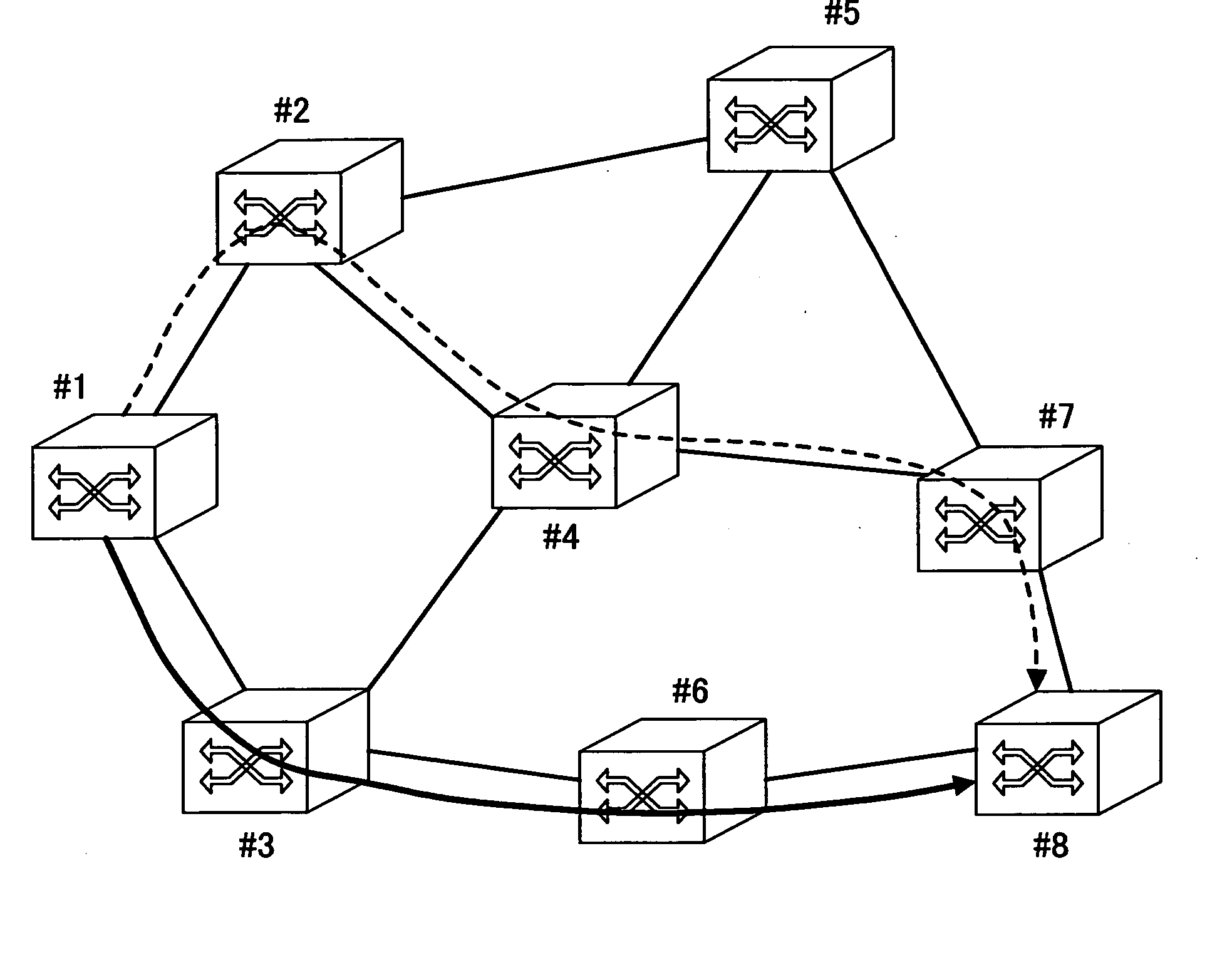
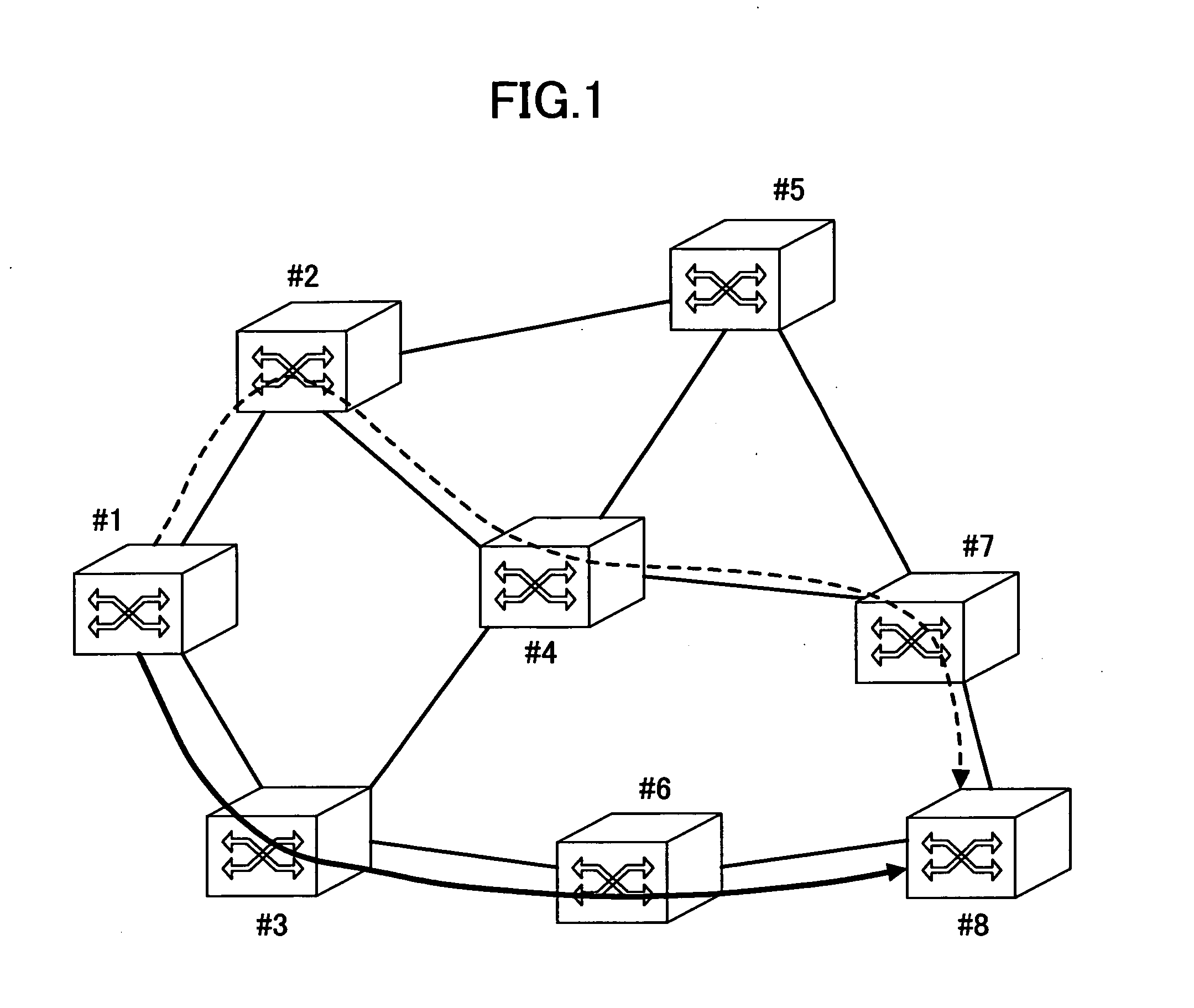
[0184] A communication network to which the backup path bandwidth keeping method of the present embodiment is applied is one shown in FIG. 1. This communication network is an optical path network defining optical paths of wavelength units, and the communication network is formed by optical cross-connect nodes for realizing cross-connection of these optical paths.

[0185] The optical paths are defined in the nodes from the source node #1 to the destination node #8 in a point-to-point manner. At each of relay nodes #3 and #6, the wavelength of the optical path is converted to avoid a collision with another optical path. The bandwidth of the optical path is 10 Gbit / s, for example, and transmission is performed with an OTN format conforming to the ITU-T G.709 specification. In addition, optical paths are accommodated in a fiber link at intervals of 50 GHz so that wavelength division multiplexing transmission of 32 wavelengths is realized in each fiber...

embodiment 1-2

Backup Path Bandwidth Keeping Method

[0196] Each node has status of use of fiber links, identification information of active optical paths to be restored by each “backup reserved” optical channel group, and risk classification number information, through which links the active optical paths pass. Associated with adding a backup optical path that uses the “backup reserved” optical channel group, or deletion of a backup optical path “backup reserved” using the optical channel group, the necessary number of optical channels that forms the optical channel group changes. In the embodiment 1-2, an additional example of an management control method for the optional channel group that is “backup reserved” in the embodiment 1-1.

[0197]FIG. 9 shows a signaling sequence of the embodiment 1-2. A master node and a slave node are defined between two nodes adjacent to each other such that a node having a larger node identification number is determined to be the master node and a node having a smal...


PUM


Abstract

In a disclosed backup path bandwidth keeping method for keeping bandwidth of a backup path to which an active path is switched when the active path becomes unavailable in nodes of a communication network, each node is connected to the same destination, and the method includes a backup path bandwidth keeping phase, for M (M is a natural number equal to or less than L) channels in L (L is a natural number) channels kept as backup path bandwidth, for notifying a destination-side node existing in a destination side of the backup path of identification number information of the M channels to be kept and identification information indicating that a path for which the bandwidth is to be kept is a backup path.

Description

TECHNICAL FIELD [0001] The present invention relates to failure recovery of paths in a large-capacity path network. BACKGROUND ART [0002] As data communications traffic in the Internet increases, it is being studied to introduce node apparatuses having a throughput no less than a T bit / s currently, and no less than 10-100 T bit / s in the near future. As means for realizing a node apparatus having such a large transferring capability, an optical router is becoming prevalent since such a capability exceeds the limit of electrical processing. As documents on the optical router, there are a document 1 (K. Shimano et al., in Technical Digest of NFOEC'2001, vol. 1, p. 5, 2001) and a document 2 (K-I Sato et al., “GMPLS-Based Photonic Multilayer Router (Hikari Router) Architecture”, An overview of traffic engineering and signaling technology, IEEE Comm. Mag. vol. 40, pp. 96-101, March 2002), and the like. [0003] As for the optical router, management of an optical communication network is per...

Claims


Application Information

Patent Timeline
IPC IPC(8): H04J3/14H04L45/24H04B1/74H04L45/247H04L69/40H04M3/00
CPCH04J14/0284H04J14/0291H04J14/0295H04L45/00H04Q2011/0088H04Q11/0062H04Q2011/0073H04Q2011/0081H04L45/22H04L45/247
Inventor IMAJUKU, WATARUSHIMANO, KATSUHIROTAKIKAWA, YOSHIHIROOKI, EIJIOKAZAKI, YASUTAKA
Owner NIPPON TELEGRAPH & TELEPHONE CORP
Why Eureka
Try Eureka