
Separators for use in alkaline cells having high capacity

a technology of alkaline cells and separators, applied in the field of separation, can solve the problems of reducing the useful electrochemical capacity reducing the potential life of the cell, and limiting the high-rate discharge performance of the electrochemical cell

Inactive Publication Date: 2006-11-16
ROVCAL +1
View PDF104 Cites 68 Cited by
  • Summary
  • Abstract
  • Description
  • Claims
  • Application Information

AI Technical Summary

Benefits of technology

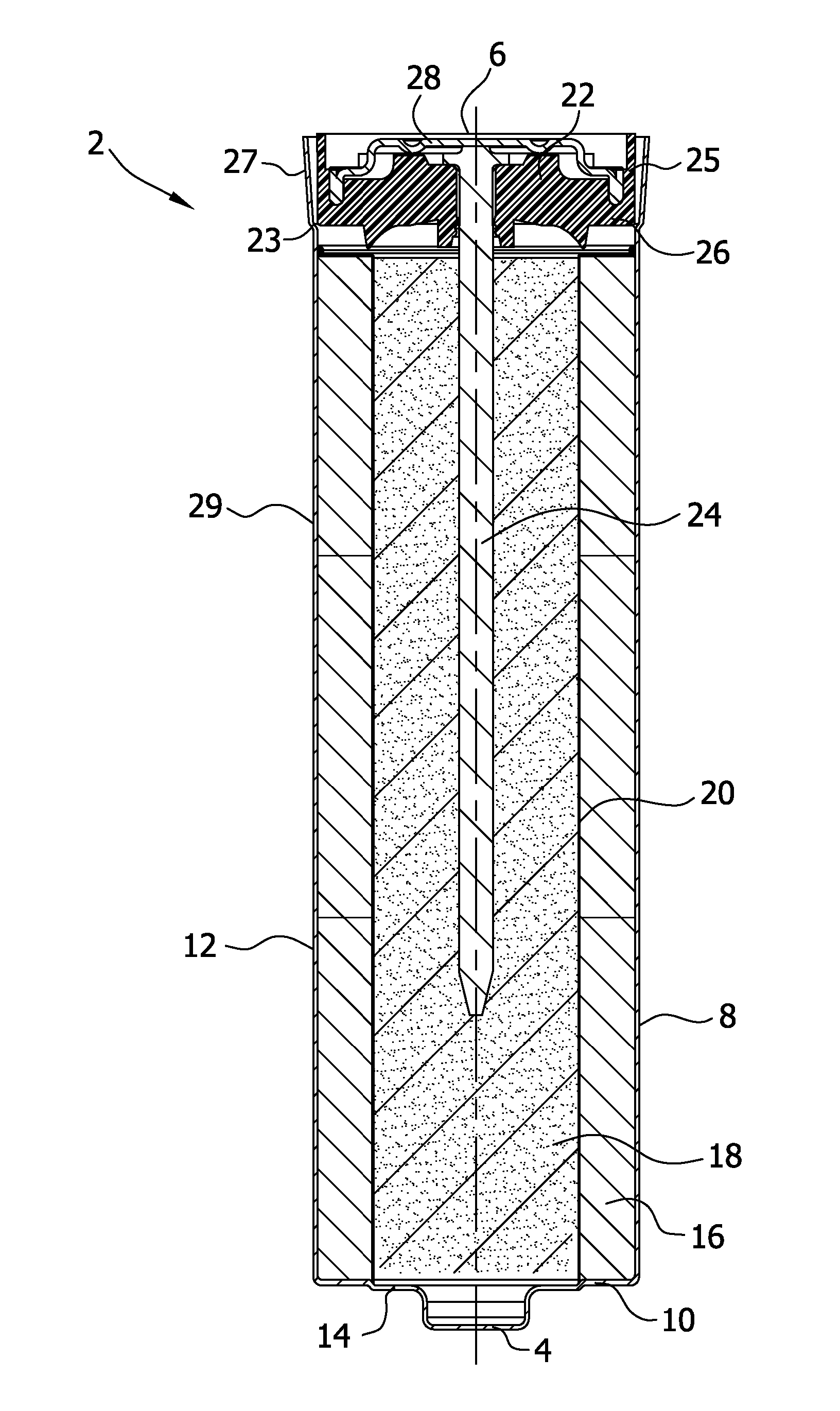
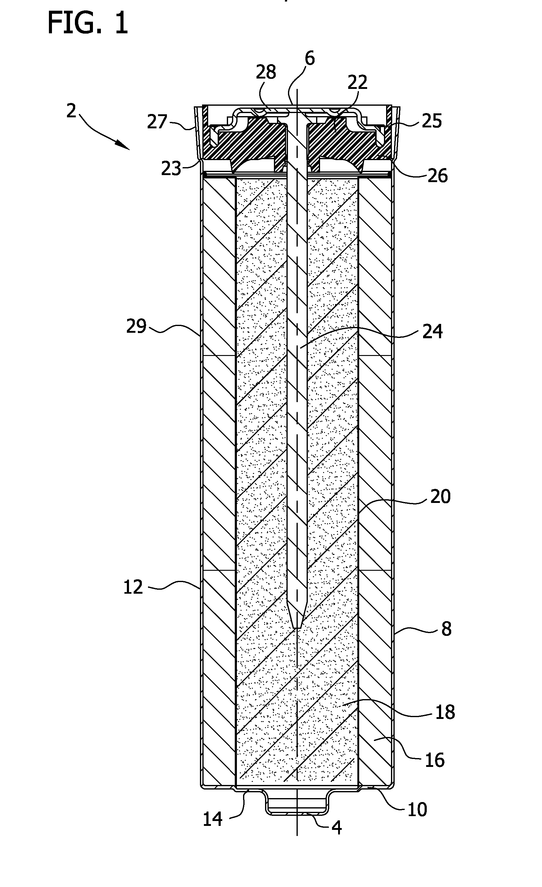
[0017] The present invention is still further directed to one or more of the above-referenced electrochemical cells, wherein the separator comprises a first layer facing the anode, a second layer facing the cathode, and a middle layer disposed between the first and second layers, wherein the middle layer comprises particles of a clay additive, or alternatively a metal sulfide additive.
[0018] The present invention is still further directed to one or more of the above-referenced electrochemical cells, wherein the separator comprises a first layer facing the anode, a second layer facing the cathode, and a middle layer disposed between the first and second layers, wherein the middle layer comprises particles of a metal sulfide additive, and the second layer comprises particles of a clay additive.
[0

Problems solved by technology

If the anode and cathode come into physical contact with each other in any way, an active chemical reaction occurs, resulting in an internal electrical short circuit or other reduction in the useful electrochemical capacity of the electrochemical cell.
Where a single layer of such a separator material is used, openings that are commonly present in the material permit the presence or formation of undesirable conductive paths between the cathode and the anode.
Alternatively, the use of multiple or thicker layers of separator material typically increases the volume necessary in the electrochemical cell for accommodating the separator (inactive) component, leaving less room for the active electrochemical materials, and thus potentially reducing the potential life of the cell.
The thicker separator materials also tend to increase the amount of ionic resistance between the anode and the cathode, limiting the high rate discharge performance of the electrochemical cell.
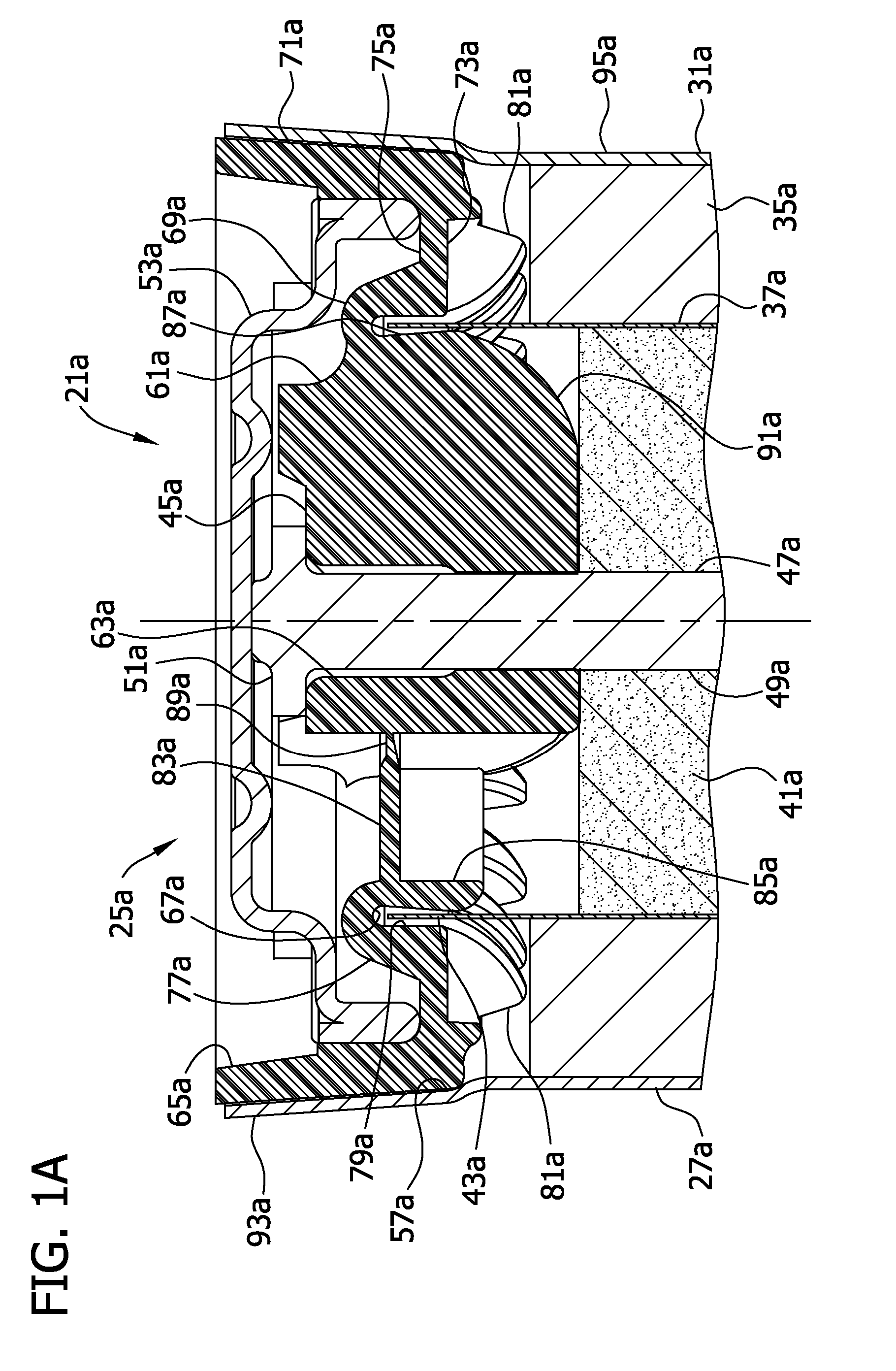
While these sealing assemblies help keep the can (electrically connected to the cathode) and the top (electrically connected to the anode) from contacting each other, electrical shorting and loss of battery life may still occur due to the transport of anode or cathode particles over the tope of the separator, resulting from separation of the separator from the sealing assembly during manufacturing, distribution, handling, or use.
However, effectively incorporating such materials in cylindrical batteries while maintaining the reliability from shorting is a challenge as compressing these thin film and membrane separator materials against the sealing assembly in the same manner as the conventional thick separators often fails to completely prevent contact between the cathode and the anode during manufacturing, distribution, transportation, handling, or use.
These forces can dislodge separator from the sealing assembly, resulting in the potential for contact between the cathode and the anode that may result in an internal electrical short circuit or other reduction in the useful electrochemical capacity of the electrochemical cell.

Method used


Image

  • Separators for use in alkaline cells having high capacity
  • Separators for use in alkaline cells having high capacity
  • Separators for use in alkaline cells having high capacity

Examples


example 1

[0414] This is an example that illustrates the efficacy of various separators' ability to effectively limit the migration of anode-fouling soluble species. The open circuit voltage (OCV) was compared for a plurality of 357-size cells made with various separators both initially and after 1 day room temperature of storage. The cathode was CuO (commercially available from Aldrich, St. Louis, Mo.), and the cell anode was a conventional alkaline Zn gel anode having conventional zinc and electrolyte concentrations.

[0415] In most cases, two layers of separator were used in the cell, one facing the cathode (“cathode side separator”), the other facing the anode (“anode side separator”). The OCV data presented below in Table 6 includes the average of two cells of the given cell type. It should be appreciated that a decrease in OCV indicates increased migration of anode-fouling soluble copper species into the anode

TABLE 6Cathode Side SeparatorAnode SideOCV, VOCV, VCategoryTypeSeparator(init...

example 2

[0417] This is an example that illustrates the ability of various separators to effectively limit the migration of anode-fouling species. As explained elsewhere, Side A of the glass tube fixture was filled with 34% KOH having a known concentration of copper ions and electrolyte free of copper ions was added to compartment B. The concentration of complex copper ions on side B was measured after 1 week at room temperature.

[0418] Referring now to Table 7, the Exclusion Test was performed on various separators to determine the Exclusion Value of soluble copper, silver, and sulfur species after storage at a temperature of 60° C. Side A of the glass fixture was filled with 34% KOH solution with 0.25 g of CuO (copper oxide) and 0.25 g of CuS powder which produce the soluble copper and sulfur species concentrations shown in columns 2 and 4. For silver exclusion determination, 0.25 g of AgO was used in side A of the AgO was used in side A of the fixture to produce silver concentrations show...

example 3

[0420] This is an example that illustrates the utility of effectively limiting the migration of anode-fouling soluble species in stored 357 size button cells. Referring now to FIG. 28, four cells having CuO cathodes were stored for five days at room temperature, followed by 60 degrees C. until the cells failed (as determined by OCV, impedance and expansion as discussed previously). The OCV was continuously measured for each cell from the first day of storage. FIG. 28 shows that cellophane separators are better than FAS 350Z separator for cells containing CuO cathodes. Also, thicker cellophane separators (SF-586, 3 mil thick) outperform the thinner separator (350P00, and SC216 both are 1 mil thick) confirming results from the Exclusion Test experiments.


PUM


Abstract

The present invention relates to an electrochemical cell comprising an anode, a cathode, and a separator disposed between the anode and cathode. More particularly, the present invention relates to an electrochemical cell comprising, among other things, a separator impregnated with, and / or coated with a layer of, a clay and / or a metal sulfide additive. The present invention additionally or alternatively relates to an electrochemical cell which comprises, among other things, a self-supporting or free-standing thin film separator. The present invention additionally or alternatively relates to an electrochemical cell which comprises, among other things, a separator, wherein at least a portion thereof is covered by an adhesive material that is bonded to the container or a sealing assembly of the cell.

Description

CROSS-REFERENCE TO RELATED APPLICATIONS [0001] This application is a continuation-in-part of, and claims priority from, U.S. patent application Ser. No. 11 / 058,665 (filed Feb. 15, 2005) and U.S. patent application Ser. No. 11 / 058,678 (filed Feb. 15, 2005). This application is also a continuation-in-part of, and claims priority from, U.S. patent application Ser. No. 11 / 055,508 (filed Feb. 8, 2005), which in turn claims the benefit of U.S. Provisional Patent Application No. 60 / 577,292 (filed Jun. 4, 2004) and is a continuation-in-part of U.S. patent application Ser. No. 10 / 914,958 (filed Aug. 9, 2004), U.S. patent application Ser. No. 10 / 914,911 (filed Aug. 9, 2004), and U.S. patent application Ser. No. 10 / 914,934 (filed Aug. 9, 2004), which all in turn claim priority from U.S. Provisional Patent Application No. 60 / 577,292 (filed Jun. 4, 2004), U.S. Provisional Patent Application No. 60 / 493,695 (filed Aug. 8, 2003), and U.S. Provisional Patent Application No. 60 / 528,414 (filed Dec. 10...

Claims


Application Information

Patent Timeline
IPC IPC(8): H01M2/16H01M2/18H01M4/50H01M4/48H01M50/414H01M50/451H01M50/466H01M50/489H01M50/491
CPCH01M2/1653H01M2/166H01M2/1673H01M2300/0014H01M2/1686H01M2/18H01M6/08H01M2/168H01M50/446H01M50/46H01M50/461H01M50/491H01M50/451H01M50/466H01M50/414H01M50/489
Inventor MORTENSEN, ERIKJIN, ZHIHONGVU, VIET H.BUSHONG, WILLIAM C.RAMASWAMI, KARATHIKKREN, KEVINDAVIDSON, GREGORY J.
Owner ROVCAL
Learn More