

Droplet discharge method, droplet discharge apparatus, manufacturing method for liquid crystal device, liquid crystal device, and electronic apparatus
a technology of droplet discharge and manufacturing method, which is applied in the direction of identification means, instruments, non-linear optics, etc., can solve the problems of difficult to control the discharge quantity of liquid material and the location of liquid material on the substrate highly accurately, drop in display quality, and non-uniform arrangement of liquid material, etc., to achieve the effect of reducing manufacturing cost, improving performance, and reducing manufacturing cos
- Summary
- Abstract
- Description
- Claims
- Application Information
AI Technical Summary
Benefits of technology
Problems solved by technology
Method used
Image

Examples
first embodiment
[0060] Embodiments of the present invention will now be described, with reference to the drawings.
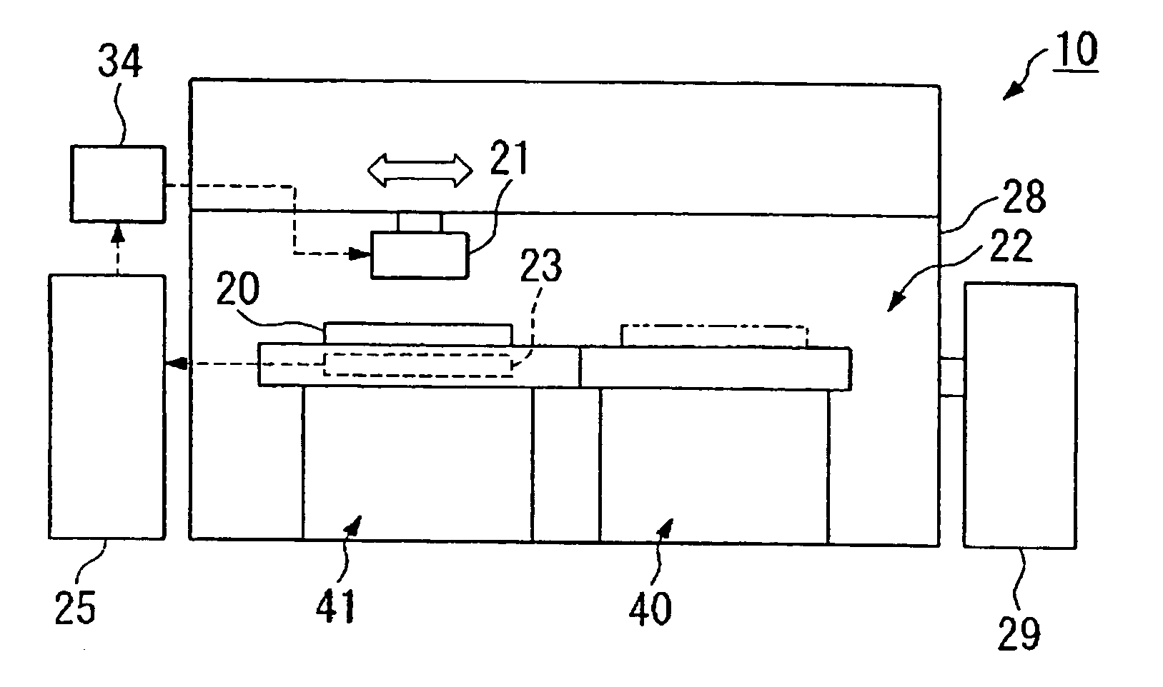
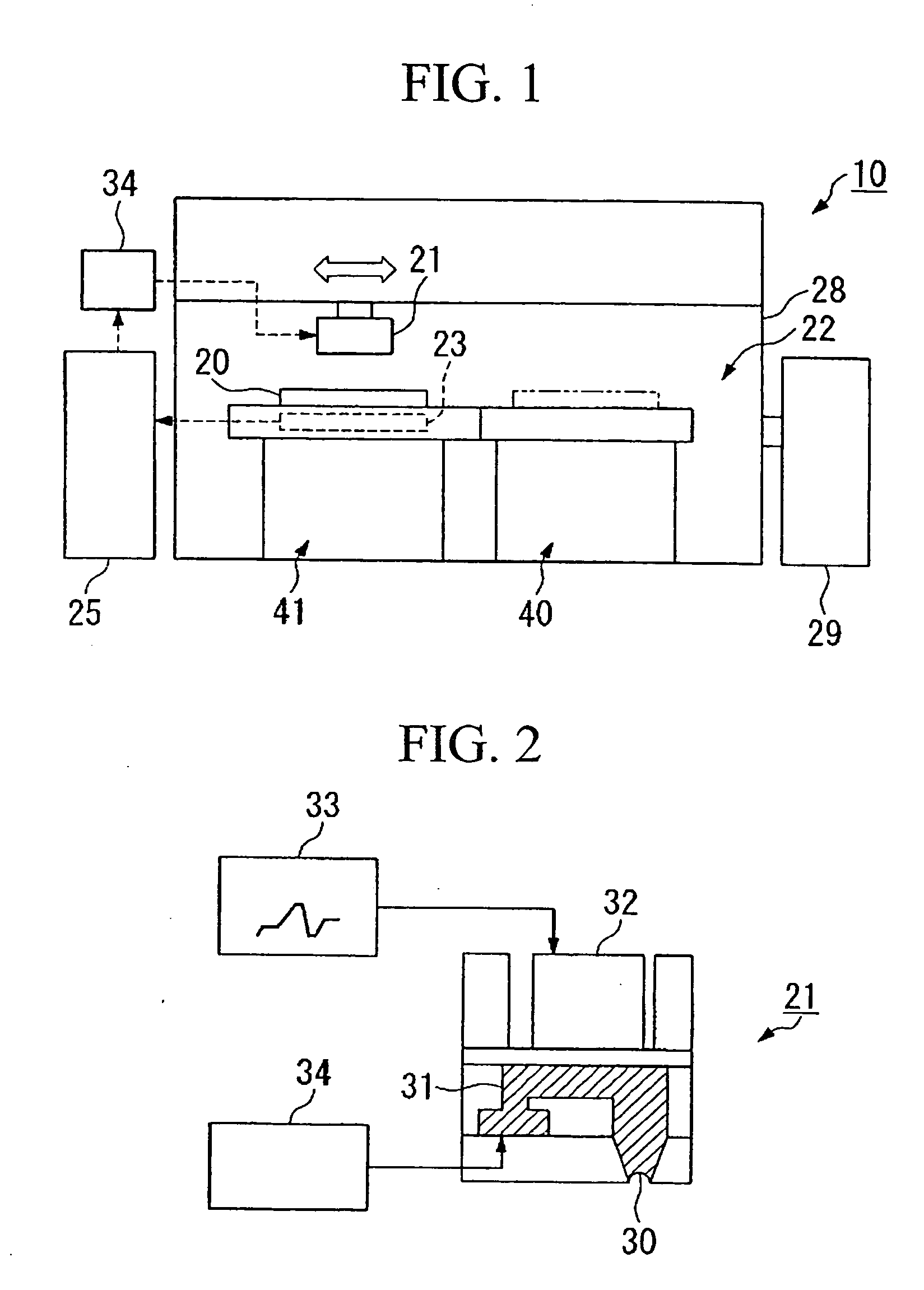
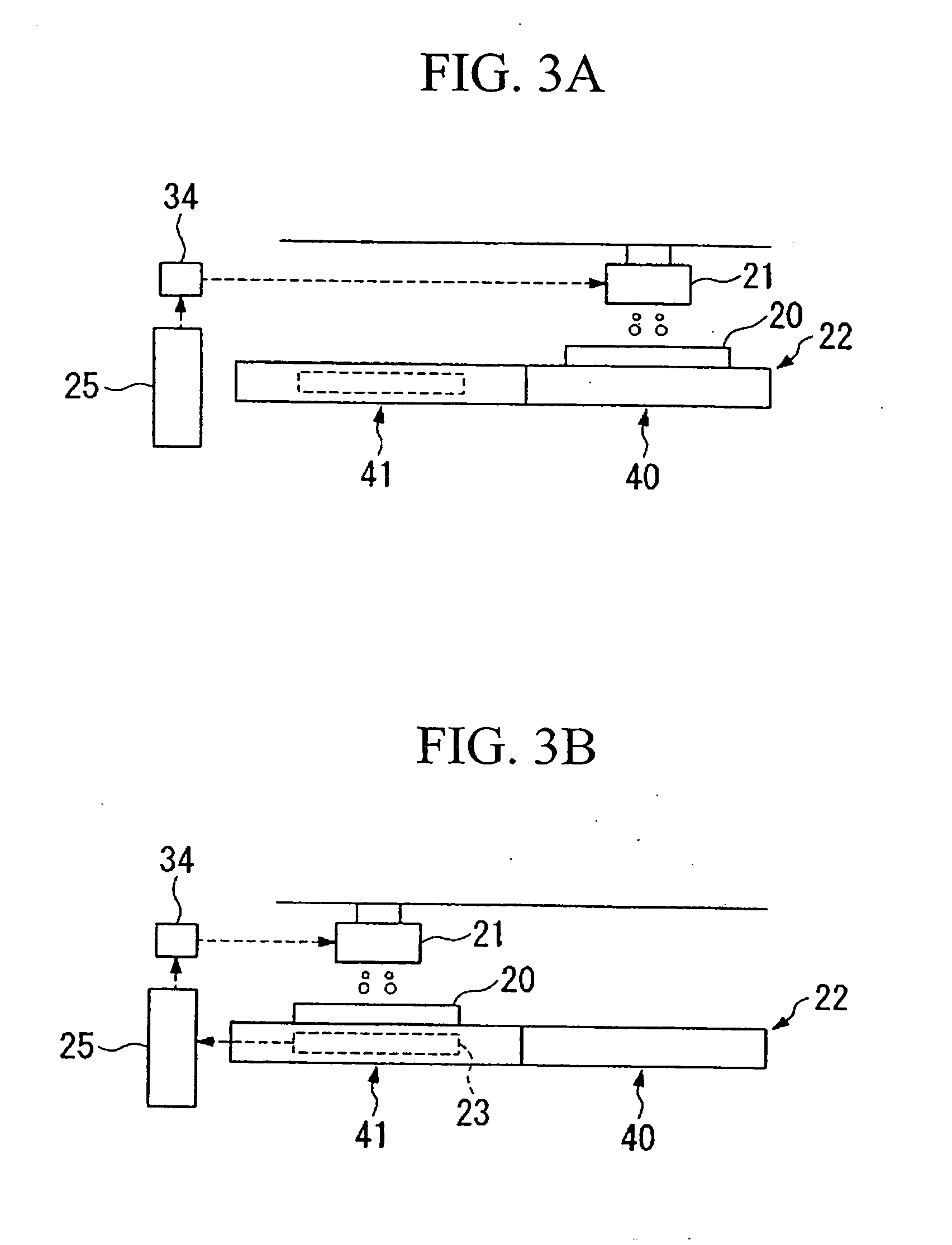
[0061]FIG. 1 schematically illustrates one example of an embodiment of a droplet discharge apparatus of the present invention. A droplet discharge apparatus 10 comprises a droplet discharge head 21 which discharges a liquid material toward a substrate 20, a substrate stage 22 on which the substrate 20 is mounted, a measuring device 23 which measures the weight of the liquid material arranged on the substrate 20, and a control unit 25 which controls these in an integrated manner. The droplet discharge head 21 and the substrate stage 22 are arranged in a chamber 28, and this chamber 28 comprises a thermostat 29, which controls the temperature therein.
[0062] For the substrate 20, various substrates may be used, such as a glass substrate, a silicon substrate, a quartz substrate, a ceramic substrate, a metal substrate, a plastics substrate, and a plastic film substrate. There is also inclu...
second embodiment
[0077] An example in which the droplet discharge method is used for a manufacturing process for a liquid crystal device will be described below.
[0078]FIG. 4 schematically illustrates a sectional structure of a passive matrix type liquid crystal device (a liquid crystal display).
[0079] The liquid crystal device 100 is of a transmission type, and has a structure such that a liquid crystal layer 103 comprising STN (Super Twisted Nematic) liquid crystal is placed between a pair of glass substrates 101 and 102. Moreover, the liquid crystal device 100 comprises a driver IC 113 for supplying a drive signal to the liquid crystal layer, and a backlight 114 as a light source.
[0080] A color filter 104 is arranged on the inner face of the glass substrate 101. The color filter 104 is formed by regularly arranging color layers 104R, 104G and 104B respectively consisting of colors of red (R), green (G) and blue (B). Between these color layers 104R (104G, and 104B), partitions 105 comprising a b...
third embodiment
[0163] In the second embodiment, the droplet discharge device of the present invention is employed for forming the passive matrix type and active matrix type liquid crystal devices, and applied to filling of the liquid crystal into the liquid crystal layer, constituting the liquid crystal device, but the present invention is not limited thereto. For example, the oriented film constituting the liquid crystal device (for example, corresponding to the oriented films 108 and 110) may be formed by using the droplet discharge method in the first embodiment.
[0164] In this embodiment, a manufacturing process in which the oriented film in the liquid crystal device is formed by using the droplet discharge apparatus of the present invention will be described. Explanation for the parts overlapping on the description relating to the oriented film explained in the second embodiment is omitted. The same members as those used in the above description are denoted by the same reference symbols.
[016...
PUM
 Abstract
Description
Claims
Application Information