Packaging for stent delivery systems

Active Publication Date: 2006-11-23
MEDTRONIC VASCULAR INC +1
24 Cites 62 Cited by

AI-Extracted Technical Summary

Problems solved by technology

However, stent insertion can cause undesirable reactions such as inflammation, infection, thrombosis, or proliferation of cell growth that occludes the passageway.
Restenosis occurs because the blood vessel wall is injured when the stent is implanted.
The arterial walls may become so thick in some instances that they sometimes protrude into the mesh of the stent.
However, because the treated stent may contain a therapeutic dr...

Method used

[0031] The packaging for a treated stent delivery system takes the form of a pouch or bag (1), as shown in FIG. 1. The pouch (1) is provided with two compartments (2,3). The compartments are formed by sealing a sheet of impermeable membrane (4) such as Tyvek® material, to a layer of laminated foil (5) an...

Benefits of technology

[0009] It is thus an object of the present invention to provide a process for packaging stents which is simple to operate, and which produces a package which optimises ambient conditions for treated stents. It is also an object to provide a package for treated stents and their associated delivery systems, which provides a barrier to oxygen, moistur...

Abstract

The present invention relates to a method of packaging and a packaging system for treated stents (9) which minimise the level of exposure of the stents to oxygen, moisture and light. The package comprises two compartments (2, 3), the compartments (2, 3) being in communication with each other via a breathable membrane (4).

Application Domain

Technology Topic

Image

  • Packaging for stent delivery systems
  • Packaging for stent delivery systems
  • Packaging for stent delivery systems

Examples

  • Experimental program(2)

Example

Example 1
[0034] The process for packaging a stent which is sterilised by gamma radiation comprises placing a coated stent, mounted on a delivery system and loaded into a coiled dispenser, into the larger of the two compartments of the pouch. In this embodiment the compartment is 280 mm long and 250 mm wide. The layer of Tyvek is located between two layers of foil, which are both of equal length, so that no portion of the Tyvek is exposed.
[0035] The moisture and oxygen absorber packs are placed in the second compartment which is 120 mm long. The Tyvek layer thus separates the scavenger packs from the stent but allows interaction between the two compartments.
[0036] In a single operation the open end of the pouch is flushed with nitrogen and vacuum-sealed, so that the two compartments are sealed together. Any excess material above the seal area is trimmed away, which eliminates the possibility of opening the pouch at this end.
[0037] The inert gas used to flush the package is preferably nitrogen. The nitrogen is flushed for between 1 and 10 seconds at a pressure of 10 to 30 psi. The vacuum draw down time is suitably 1 second, up to 10 seconds. The package may be sealed by clamping the edges of the package between upper and lower jaws of a sealing device. The seal time may be from 1 to 10 seconds, with an upper jaw seal temperature of 110 to 200° C. and a lower jaw seal temperature of 60 to 100° C. and the seal pressure may be from 30 to 100 psi.
[0038] The sealed pouch is then sterilised by gamma radiation in a conventional manner.

Example

Example 2
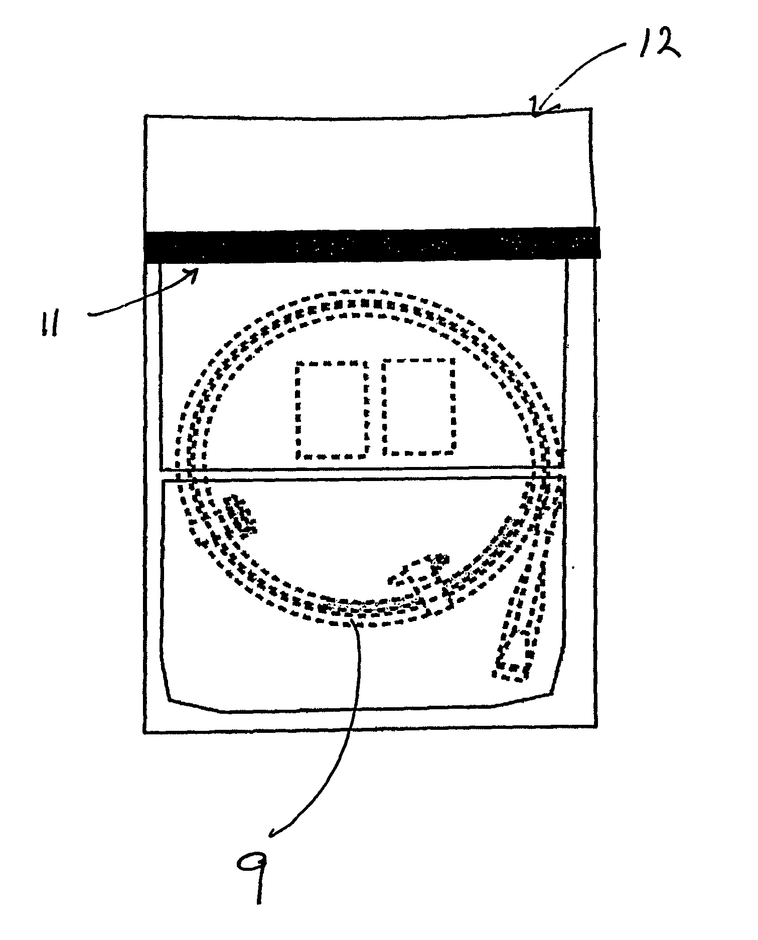
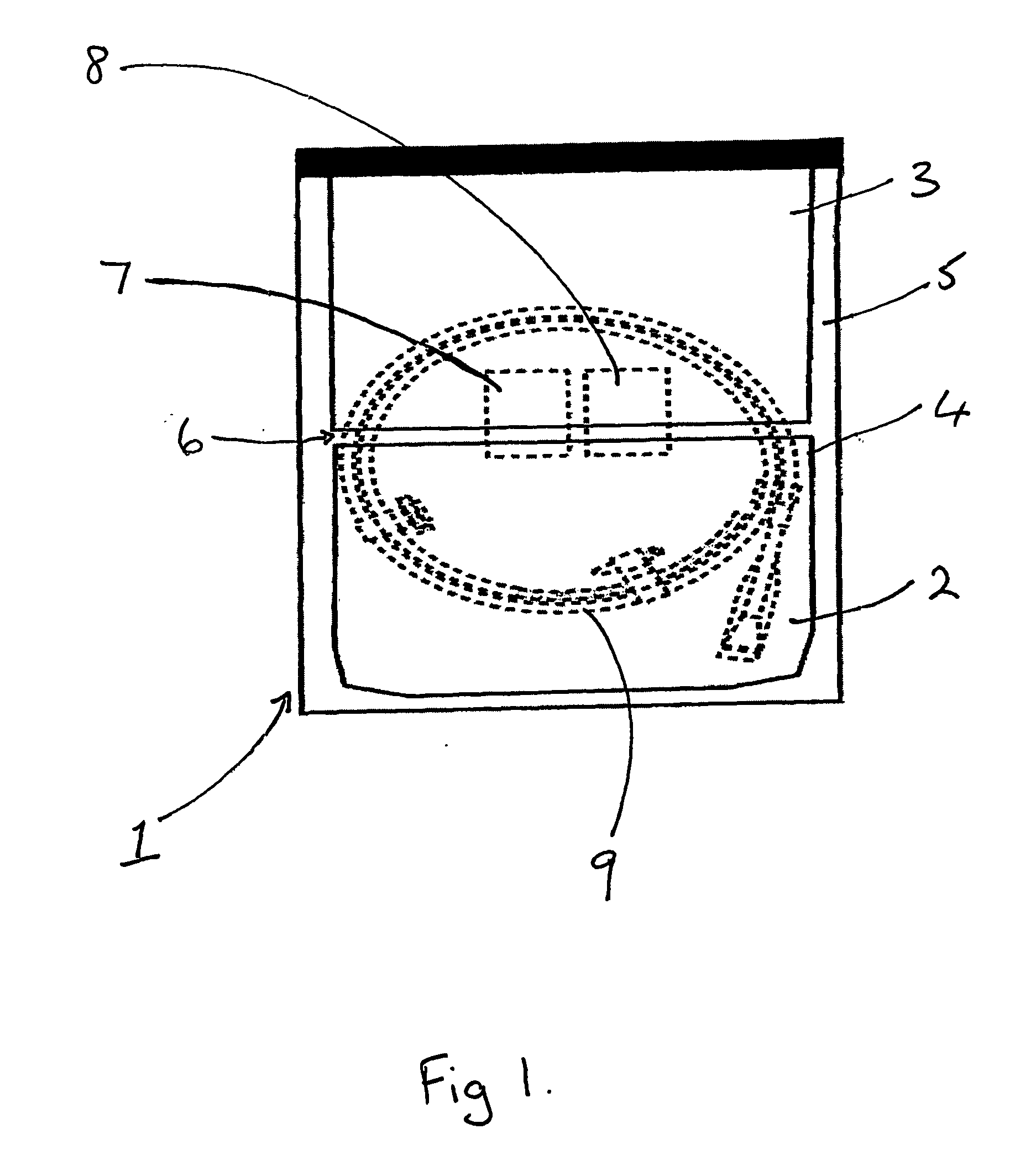
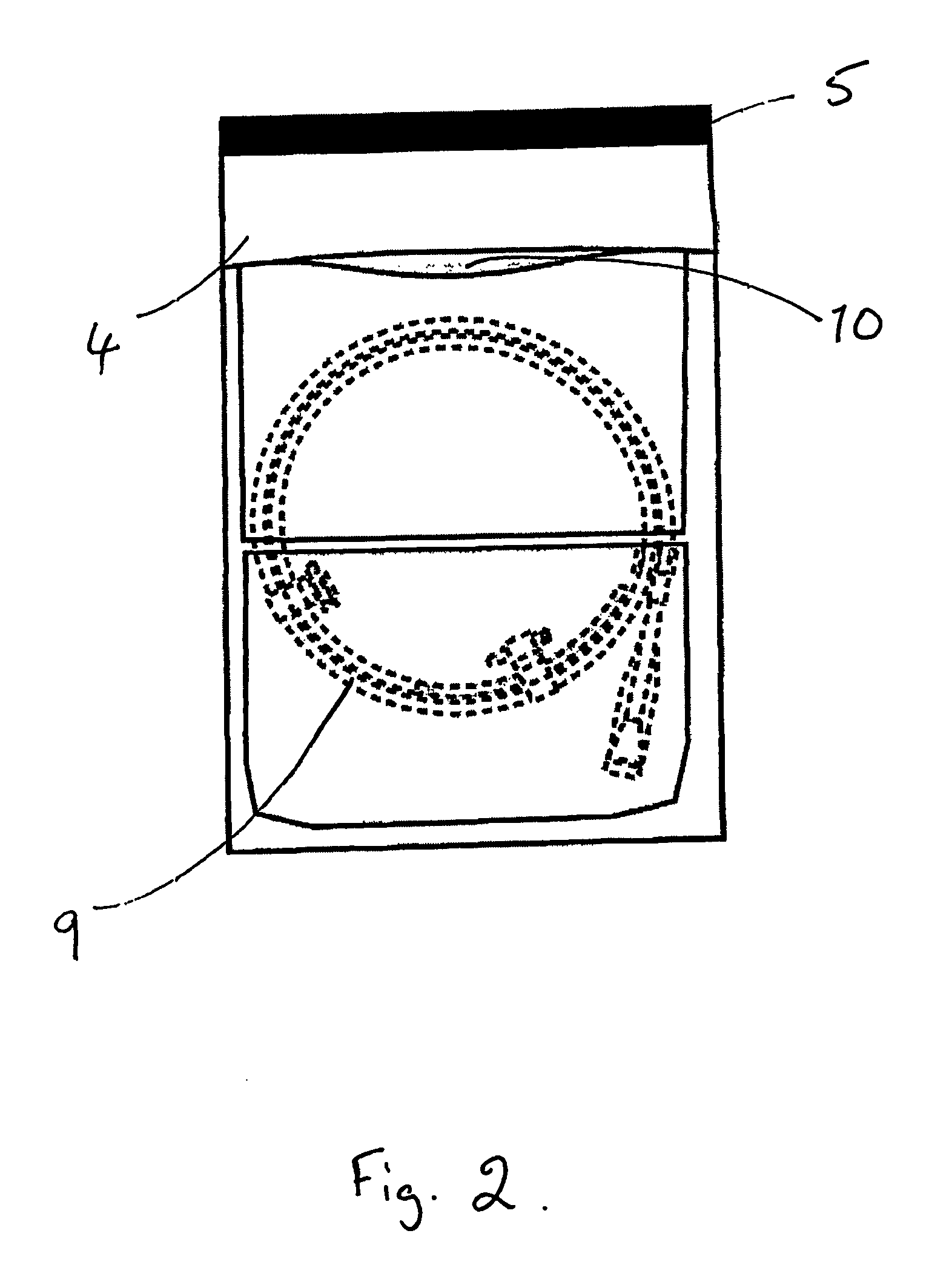
[0039] The process for packaging a stent which is sterilised by ethylene oxide is slightly different. As shown in FIGS. 2 and 3, the coated stent (9), mounted on a delivery system and loaded onto a coiled dispenser, is placed in the larger of the two compartments (3). In this embodiment the compartment (3) is 365 mm long. One of the two foil sheets (5) is shorter than the Tyvek layer (4) and the other foil sheet (5), so that a section of the Tyvek is exposed on the surface of the package (1). This exposed area (10) provides an entry and exit point for the ethylene oxide gas in the sterilisation process. The compartment (3) is then sealed at its open end, along the line (11) shown in FIG. 3, with a heated bar sealer as described in Example 1. Because one foil sheet (5) is shorter than the other it is not sealed in this operation and so one compartment (2) is left open at one end.
[0040] The package is then sterilised using ethylene oxide in a conventional manner.
[0041] Following sterilisation, oxygen and moisture absorber (7,8) packs are placed in the smaller, unsealed compartment (2) of the pouch or package (1). This compartment is 145 mm long. The package (1) is then flushed with nitrogen and vacuum-sealed, as described above, across the opening of the scavenger pack compartment (2) along the line (12). Excess pouch material between the two seal lines (10) and (12) is then trimmed away, which eliminates the possibility of opening the pouch (1) at this end which could result in the scavenger packs being released and contaminating the stent.
[0042]FIG. 4 shows the package (1) being opened at one end to remove the stent, and the absorber packs (7,8) being retained in compartment (2).
[0043] The words “comprises/comprising” and the words “having/including” when used herein with reference to the present invention are used to specify the presence of stated features, integers, steps or components but does not preclude the presence or addition of one or more other features, integers, steps, components or groups thereof.

PUM

no PUM

Description & Claims & Application Information

We can also present the details of the Description, Claims and Application information to help users get a comprehensive understanding of the technical details of the patent, such as background art, summary of invention, brief description of drawings, description of embodiments, and other original content. On the other hand, users can also determine the specific scope of protection of the technology through the list of claims; as well as understand the changes in the life cycle of the technology with the presentation of the patent timeline. Login to view more.

Similar technology patents

Dry polymer hydration apparatus and methods of use

InactiveUS20060107998A1Reduce air introductionSimple operationFlow mixersMixing methodsInjectorImpeller
Owner:SCHLUMBERGER TECH CORP

Car Navigation Apparatus

Owner:MITSUBISHI ELECTRIC CORP

Mobile communication terminal

Owner:MITSUBISHI ELECTRIC CORP

Classification and recommendation of technical efficacy words

Why Eureka
Try Eureka