

Variable wavelength radiation source
a radiation source and variable wavelength technology, applied in the field of ultraviolet radiation emitting devices, can solve the problems of not providing any exit port, no way for apparatuses to emit transformed ultraviolet radiation, use of ozone producing lamps/tubes,
- Summary
- Abstract
- Description
- Claims
- Application Information
AI Technical Summary
Benefits of technology
Problems solved by technology
Method used
Image

Examples
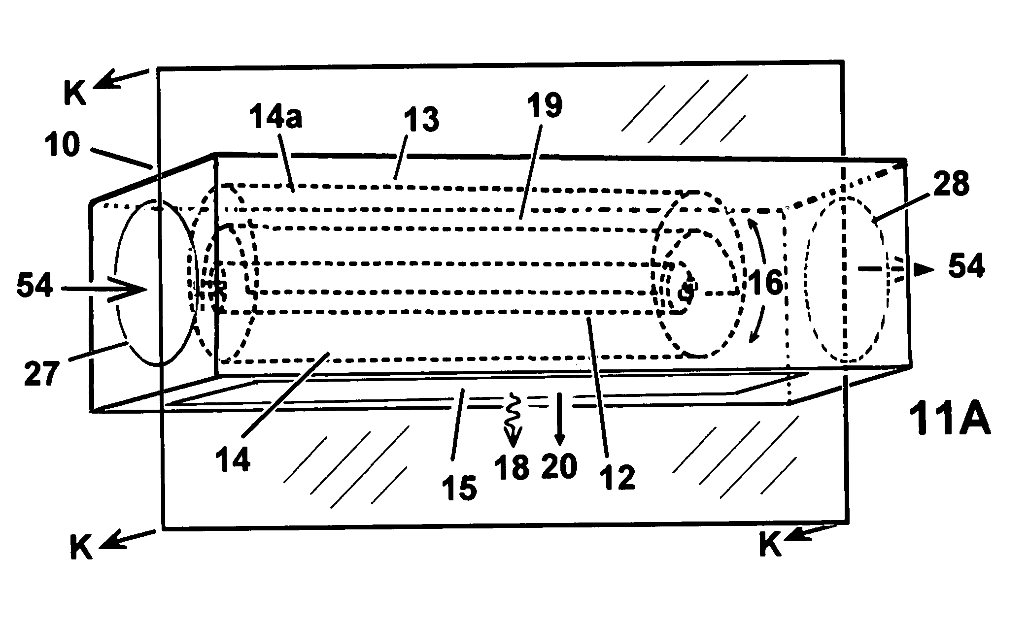
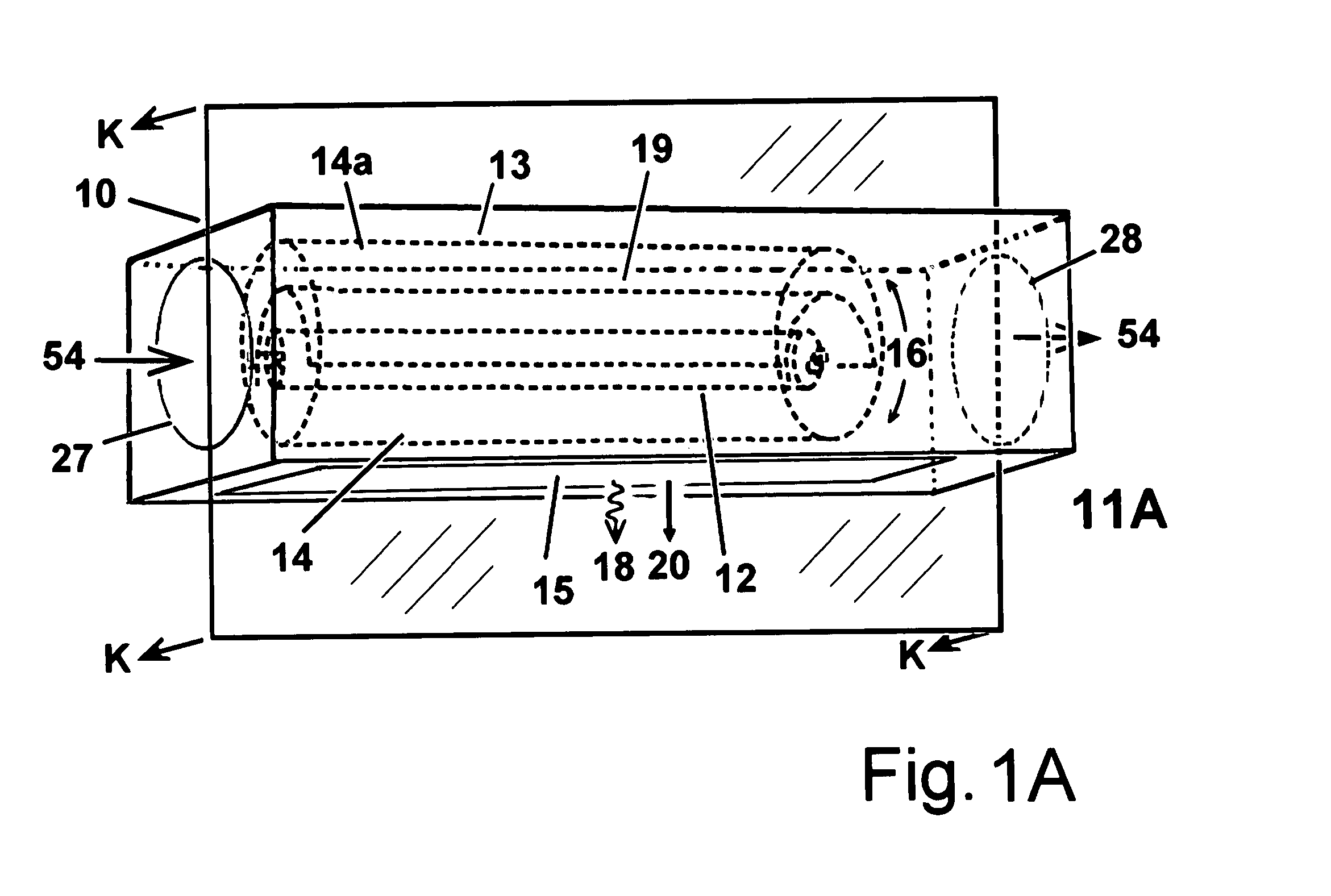
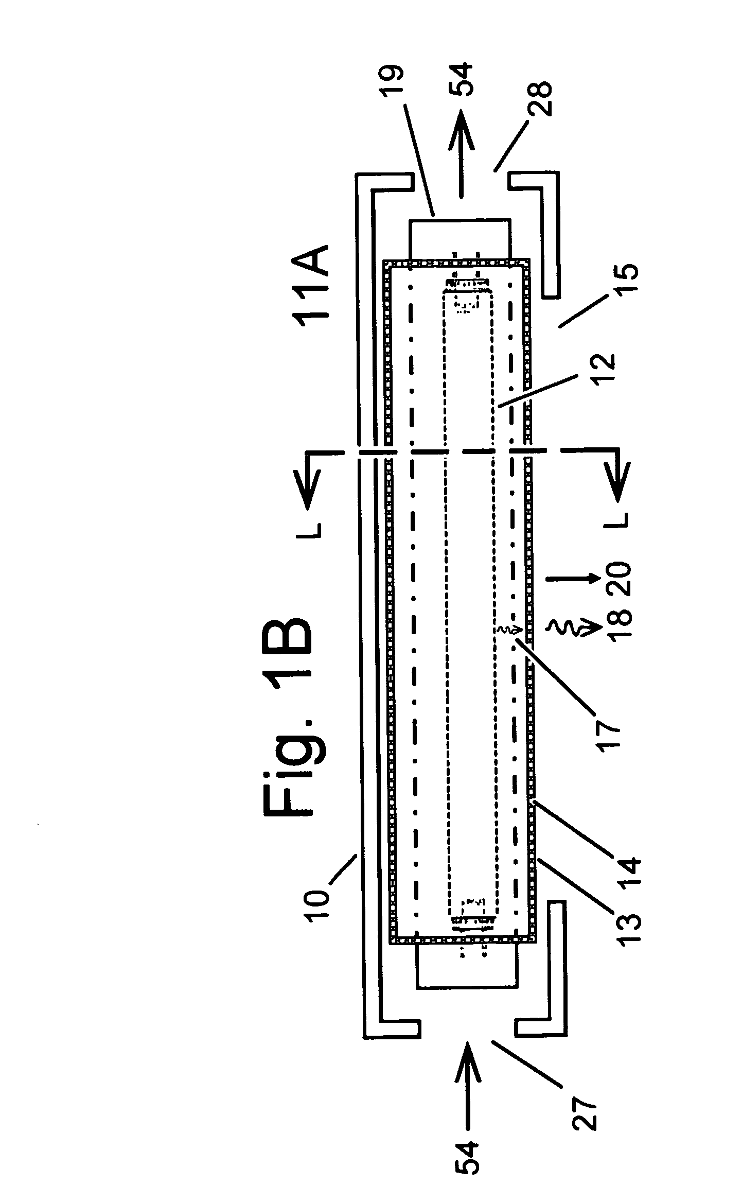
first embodiment
[0051]FIG. 1J is an expanded view of a portion of the wall of the cylindrical WT filter 13 of apparatus 11B, showing a variation of the first embodiment where the WT materials are associated with fiber or wire like shapes that form a woven mesh comprising the material of the cylindrical WT filter 13. As an example, a woven fiber-glass cloth wherein the individual fibers have WT material 14 included in the composition. As a variation, the WT material 14, (14a, 14b, etc.) can also be bonded, fused, glued, blended, conjoined, fastened, united, merged, joined, integrated, or otherwise associated with the outside of the fiber or wire-like shape.
second embodiment
[0052] In the present invention one or more primary UV radiation sources are placed behind at least one substantially flat WT filters. Portions of the flat filter(s) are coupled with different WT materials each of which is capable of producing a transformed radiation upon irradiation by the primary UV radiation. In this embodiment, another portion of a substantially flat filter can remain transparent to the primary UV radiation. To easily switch between different radiation emissions, the device moves the substantially flat WT filter(s) into position such that the desired WT material, the transparent region, or a void or slit in the flat filter, lies between the primary UV radiation source and the radiation exit port of the apparatus. This movement can be accomplished by a mechanical or electrical means through a linear lateral or planar rotating motion of the substantially flat WT filter, such that none, one, or more than one of the WT materials are placed between the primary light ...
third embodiment
[0063] In the present invention one or more primary UV radiation sources are placed behind at least one substantially flat disk shaped WT filter. Portions of the substantially flat disk shaped filter(s) are coupled with different WT materials each of which is capable of producing a transformed radiation upon irradiation by the primary UV radiation. In this embodiment, another portion of the substantially flat disk shaped filter(s) can remain transparent to the primary UV radiation, or even have a portion of the substantially flat disk shaped filter(s) missing. To easily switch between different radiation emissions, transformed or un-transformed, the device rotates the substantially flat disk shaped WT filter(s) such that the desired WT material, the transparent region, or a void or slit in the flat filter, lies between the primary UV radiation source and the radiation exit port of the apparatus. This movement can be accomplished by a mechanical or electrical means through a rotating...
PUM
 Abstract
Description
Claims
Application Information