Device for detection of surface condition data

a technology for condition data and devices, applied in the direction of braking systems, traffic control systems, electrical/magnetic means, etc., can solve the problems of low reliability of sensors, contaminated air between sensors and road surfaces, and the arrangement of sensors, so as to improve the reliability of detectors

Inactive Publication Date: 2006-11-23
LIWAS
View PDF28 Cites 29 Cited by
  • Summary
  • Abstract
  • Description
  • Claims
  • Application Information

AI Technical Summary

Benefits of technology

[0050] The present invention further relates to a road surface detector means to be mounted on a vehicle for contact-less detection of the surface properties of the road surface and providing an output accordingly, comprising a radiation transmitter directed to the road surface and at least one receiver for receiving the radiation returned from the road surface and providing an output accordingly, wherein the detector means comprises washing means for the transmitter and the at least one receiver for recurrently flushing thereof. This detector means may be used with the device and the system disclosed previously. The purpose of t...

Problems solved by technology

The different arrangements of the sensors have each their drawback.
Sensors arranged along the roadside and above the road surface have to be about 4.5 meters above to road surface to allow all types of vehicles to pass, and the air between the sensor and the road surface will be contaminated with particles raised from the road surface by the passing vehicles, in particular when the road surface is wet or covered with sled or snow, and the reliability of the sensor is therefore low under the weather conditions at which the warnings of slippery surface conditions are of importance.
Sensors embedded in the road surface and measuring the properties thereof from below through a transparent lid, suffer from contamination of the upper surface of the lid and development of scratches, which ruin the operation of the sensor.
Sensors mounted on the vehicle measure from above close to ...

Method used


Image

  • Device for detection of surface condition data
  • Device for detection of surface condition data
  • Device for detection of surface condition data

Examples


Embodiment Construction

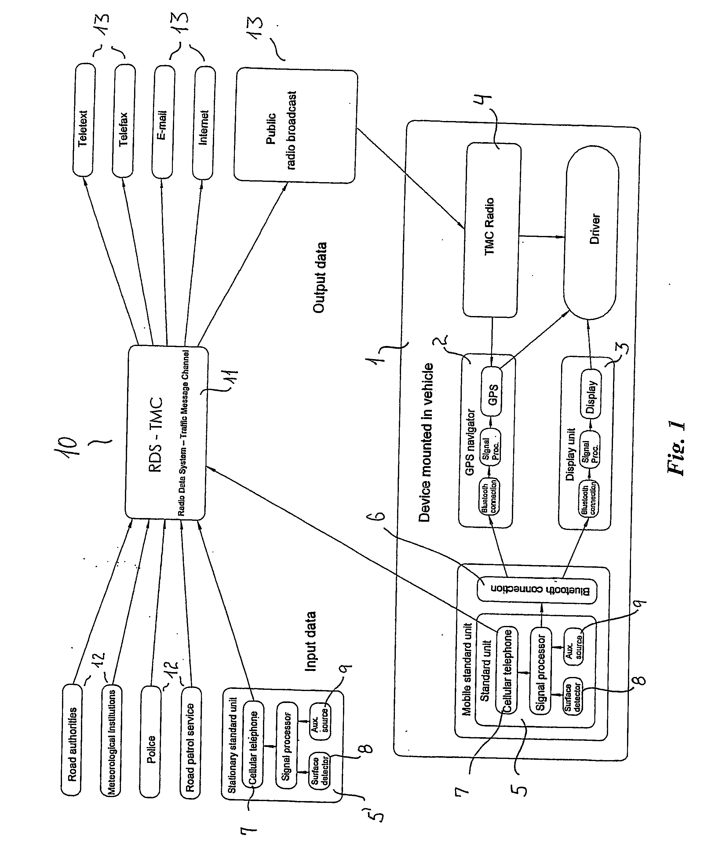
[0071] The system shown in FIG. 1 comprises a device 1 for mounting in a vehicle, comprising a standard GPS device 2 used e.g. for a navigation system, a display unit 3, which also may be used for other purposes, e.g. for the navigation system, a radio 4 for receiving TMC, and a standard sensor device 5, communicating with the GPS device 2 and the display unit 3 via a wireless Bluetooth data connection 6. The standard sensor device 5 may also be used at stationary roadside measurement stations 5′. A radio transmitter 7 of the standard sensor device 5 communicates road surface property data achieved from the road surface detector means 8, from the GPS device 2 and other possible sources 9, such as the ABS, to the stationary part 10 of the system as well as to similar devices 1 mounted in other vehicles by means of transmitting the data as data packages on a common communication channel. The mutual direct exchange of data between similar devices 1 will normally be limited in distance,...


PUM


Abstract

A device is disclosed for detection of surface properties or conditions, in particular detection of water, snow and ice and in particular to read surfaces by means of detector means mounted on individual vehicles, and transmitting the data from the vehicle, preferably together with position data of the vehicle, to be used by drivers of other vehicles for warning of slippery road conditions ahead of the vehicle. According to a particular aspect, it has been realised that the fact that polarized light which is mirror reflected by e.g. ice or water on a surface, preserves its polarization, whereas polarized light which is diffuse reflected largely becomes depolarized, may be utilised to separate the two types of reflection and thus provide a much more compact sensor device for surface properties, in which the light may be emitted close to or parallel to the road surface normal.

Description

[0001] The present invention relates to detection of surface properties or conditions, in particular detection of water, snow and ice and in particular to road surfaces by means of detector means mounted on individual vehicles. The detected properties are according to one aspect of the invention transmitted from the vehicle, preferably together with position data of the vehicle, to be used by drivers of other vehicles for warning of slippery road conditions ahead of the vehicle. BACKGROUND [0002] Detectors for determining the properties of a road surface are well known in the art, including stationary detectors arranged along the roadside and above the surface, detectors arranged beneath the road surface as well as detectors arranged on the vehicles. [0003] A simple principle for contact-less measurement is disclosed in U.S. Pat. No. 4,274,091 by Decker, in which a series of light pulses is directed towards the road surface by a light emitter with a chopper wheel, and the intensity ...

Claims


Application Information

Patent Timeline
IPC IPC(8): G08G1/09B60T8/172G01N21/21G08G1/0965G08G1/0967
CPCB60T8/172G08G1/096791G01N21/21B60T2210/12G06V20/56G08G1/0967G08G1/048G08G1/09
Inventor FRIDTHJOF, JACK
Owner LIWAS
Why Eureka
Try Eureka