
Apparatus and method for operating plasma display panel

a plasma display panel and apparatus technology, applied in the field of apparatus and methods for operating plasma display panels, can solve the problems of deteriorating image quality of plasma display panels, occurrence of peaking noise, unstable wall charges in scan electrodes y and sustain electrodes z, etc., to prevent peaking noise, improve image quality, and improve brightness

Inactive Publication Date: 2006-11-23
LG ELECTRONICS INC
View PDF3 Cites 18 Cited by
  • Summary
  • Abstract
  • Description
  • Claims
  • Application Information

AI Technical Summary

Benefits of technology

[0018] An object of the present invention is to improve brightness.
[0019] An object of the present invention is to improve image quality.
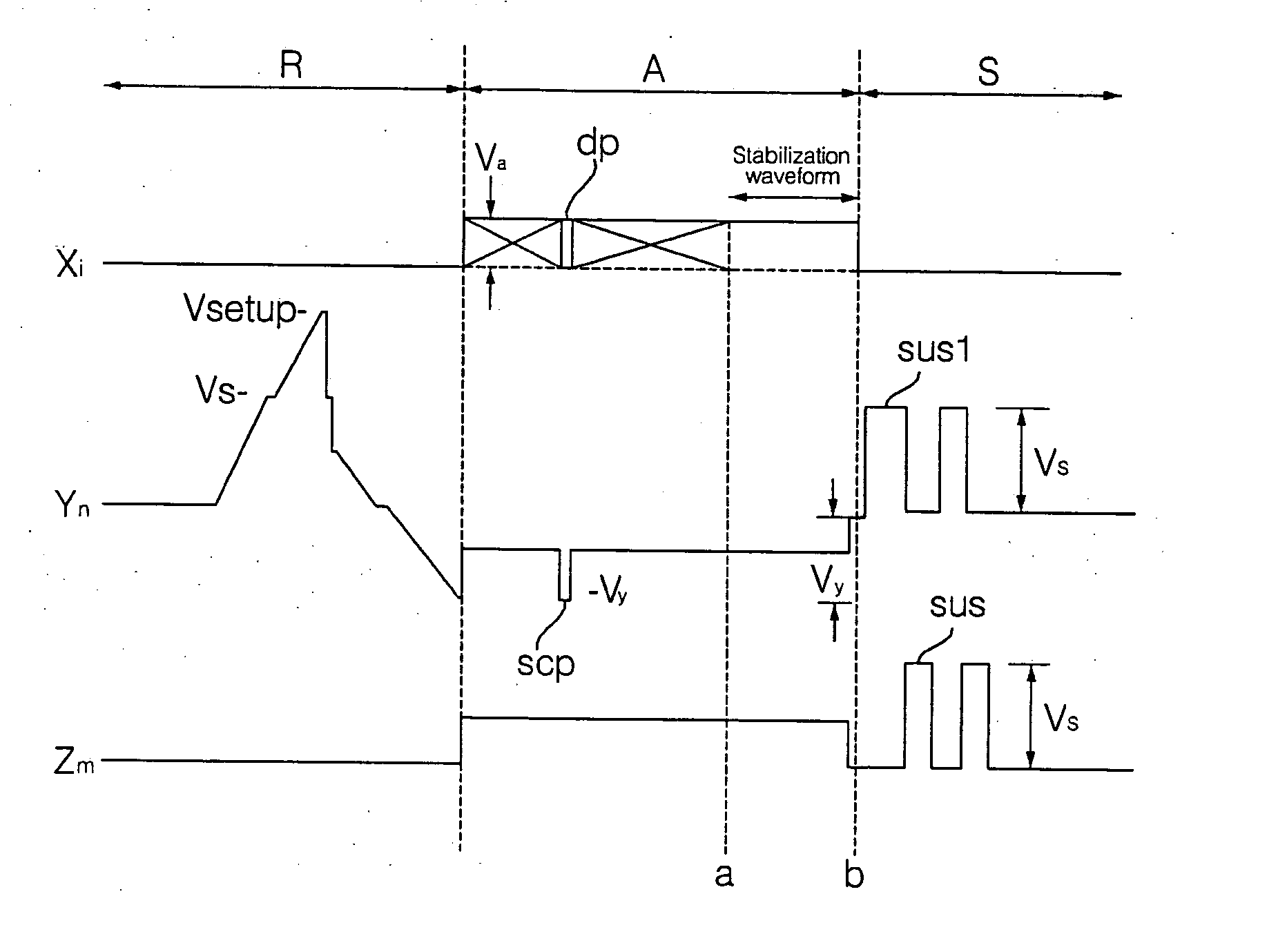
[0020] It is another object of the invention to provide an apparatus and method for operating a plasma display panel, which applies a stabilization waveform signal to an address electrode at a specific time at which video data is completely recorded in the address electrode, and prevents peaking noise from being received from a scan electrode and a sustain electrode.
[0026] In other words, after data is completely recorded in the address electrode, the PDP apparatus floats the address electrode, such that it prevents peaking noise from being generated. Therefore, the PDP apparatus prevents wall charges formed in the scan electrode and the sustain electrode are eliminated by the peaking noise, such that it can stably perform a discharge operation.

Problems solved by technology

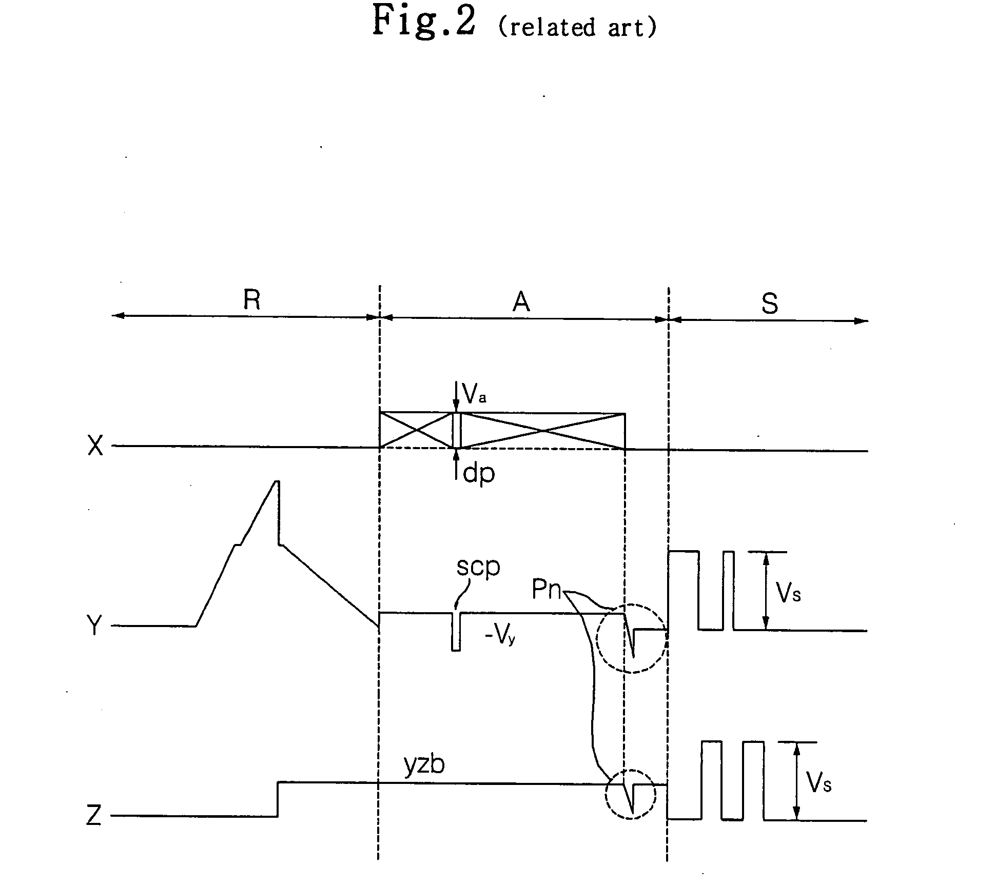
In this method, a leakage current instantaneously occurs in the scan electrode Y and the sustain electrode Z at a specific time at which data is completely recorded in the address electrode X during the address period A, resulting in the occurrence of peaking noise.
If the peaking noise (Pn) or a voltage spike occurs at the end of the address period A, data record operation is not stably completed, Hence, wall charges formed in the scan electrode Y and the sustain electrode Z become unstable.
Although the sustain pulse (sus) is applied to the scan electrode Y and the sustain electrode Z during the sustain period S, a sustain discharge is not correctly generated, resulting in deterioration of image quality of the plasma display panel.
If the peaking noise or the voltage spike occurs in the PDP, wall charges are excessively formed in the scan electrode Y and the sustain electrode Z there may arise overcharge, resulting in the sputtering of a brilliant spot.
Alternatively, the wall charges are removed by the peaking noise (Pn), the degree of sustain discharge is lowered such that erroneous discharge occurs, resulting in deterioration of brightness and image-quality characteristics of the plasma display panel.

Method used


Image

  • Apparatus and method for operating plasma display panel
  • Apparatus and method for operating plasma display panel
  • Apparatus and method for operating plasma display panel

Examples


Embodiment Construction

[0050]FIG. 3 is a perspective view illustrating a three-electrode AC surface-discharge PDP structure. As shown in FIG. 3, the three-electrode AC surface-discharge PDP structure includes a front substrate A and a rear substrate B. The front substrate A includes a scan electrode 1 and a sustain electrode sequentially formed. The front substrate A further includes a dielectric layer 3 formed on the scan electrode 1 and the sustain electrode 2, and a dielectric passivation layer 4 formed on the dielectric layer 3.

[0051] The scan electrode 1 includes a transparent electrode 1a having a relatively wide width, formed of a transparent electrode material, indium tin oxide (ITO), for visible-ray transmission; and a bus electrode 1b having a relatively narrow width, formed of a metal material to compensate for surface resistance of the transparent electrode 1a. Similar to the scan electrode 1, the sustain electrode2 includes a transparent electrode 2a and a bus electrode 2b. The transparent e...


PUM


Abstract

An apparatus and method for operating a plasma display panel (PDP) capable of removing or preventing peaking noise or voltage spike is disclosed. After substantial video data is completely recorded in the address electrode and / or after the last scan pulse or signal on the last scan electrode, the apparatus floats the address electrode or maintains the address electrode at a predetermined voltage, such that it prevents peaking noise from being received from the scan electrode and the sustain electrode, resulting in no erroneous discharge. As a result, the apparatus improves an image quality of the PDP, and increases operation efficiency of the PDP including use of single scan rather than dual scan.

Description

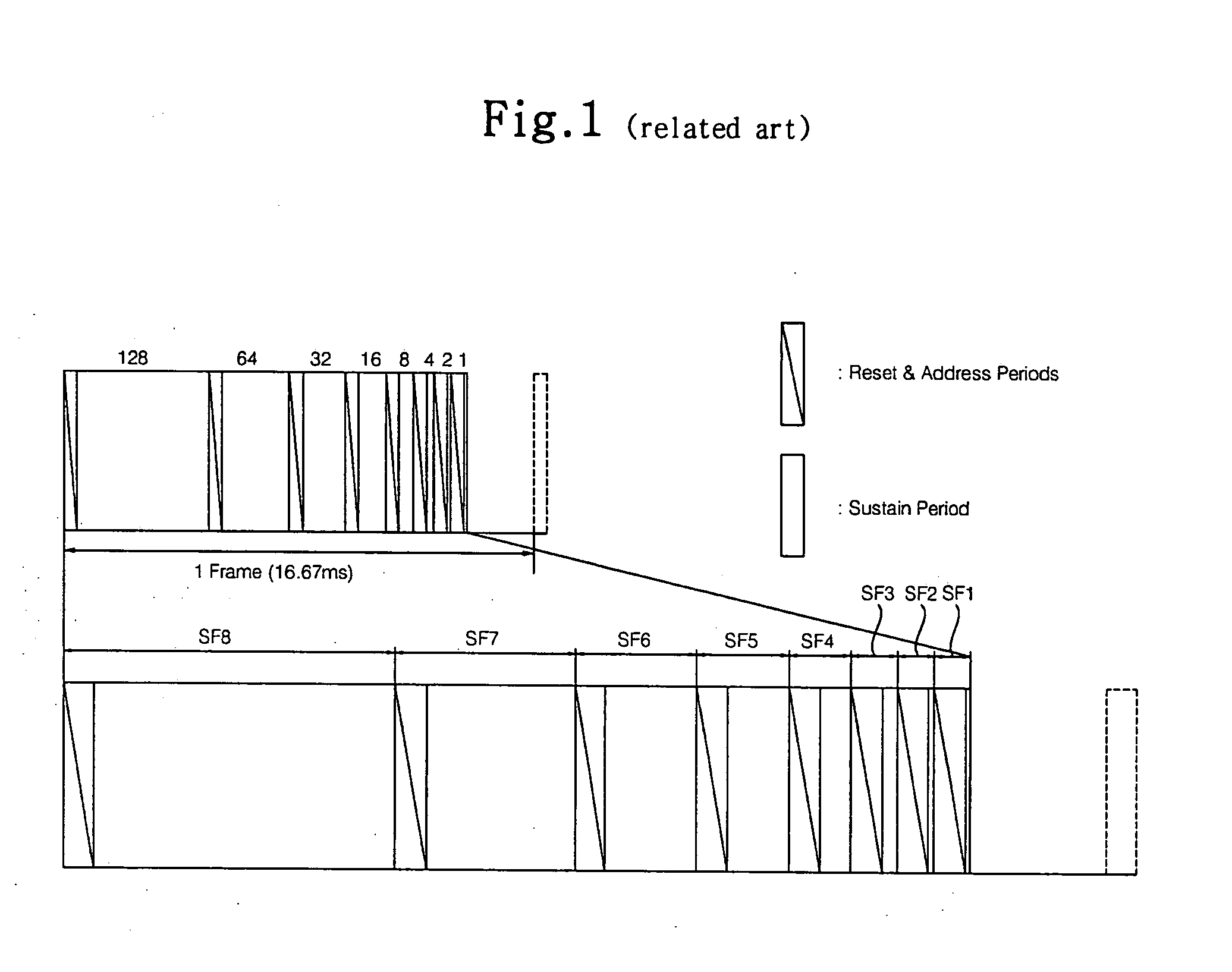
BACKGROUND OF THE INVENTION [0001] 1. Field of the Invention [0002] The present invention relates to a display device and more particularly, an apparatus and a method for operating a plasma display panel. [0003] 2. Background of the Related Art [0004] Generally, a plasma display panel (PDP) performs luminescence of a fluorescent substance using a Vacuum Ultraviolet ray of 147 nm generated during the discharge time of He+Xe gas, Ne+Xe gas, or He+Ne+Xe gas, such that it can display an image including character or graphic data. FIG. 1 illustrates the method to provide grey level or scale in a PDP. [0005] As shown, a single frame is divided into a plurality of subfields having different light-emission numbers, such that the divided subfields are driven according to a time-division scheme. Each subfield includes a reset period R for generating a uniform discharge operation, an address period A for selecting a discharge cell, and a sustain period S for implementing a grey level according ...

Claims


Application Information

Patent Timeline
IPC IPC(8): G09G3/28G09G3/293G09G3/20G09G3/291G09G3/294
CPCG09G3/293G09G3/296G09G3/294
Inventor AN, YANG KI
Owner LG ELECTRONICS INC
Learn More