Image forming apparatus, process cartridge and image forming method

a technology of image bearing parts and cleaning blades, applied in electrographic process apparatus, instruments, optics, etc., can solve the problems of insufficient cleaning performance of cleaning blades for removing toner remaining on image bearing parts, long time, and high cost of paper and ink. , to achieve the effect of high durability

Active Publication Date: 2006-11-30
RICOH KK
View PDF28 Cites 38 Cited by
  • Summary
  • Abstract
  • Description
  • Claims
  • Application Information

AI Technical Summary

Benefits of technology

[0014] Because of these reasons, the present inventors recognize that a need exists for a hig

Problems solved by technology

However, these image formations take a long time and cost of paper and ink therefore is expensive.
Therefore, to make a poster and a presentation material, the speed and cost of production cause problems.
But, as the particle size of a toner decreases, cleaning performance by a cleaning blade for removing the toner remaining on an image bearing member becomes insufficient.
As a result, the image quality significantly deteriorates.
Further, small toner particles can slip through the cleaning blade since the friction between the image bearing member and the cleaning blade can cause the cleaning blade to vibrate.
Consequently, the quality of images deteriorates.
When a large amount of toner has slipped through the cleaning blade, the obtained resultant images may be abnormal images having streaks.
In addition, such toner particles that slip past the leaning blade attach to a charging roller and make the resistance and voltage thereof uneven, which may result in the occurrence of white streaks in an obtained image.
An image forming apparatus using this image bearing member can form quality images for a while but has a drawback that the surface free energy of the image bearing member increases over repetitive use, which leads to deterioration of the quality of obtained images.
But since the surface layer of amorphous silicon containing fluorine is formed by a gas phase method, cost of the image bearing member is expensive.
In addition, there is no specific description about the cleaning performance for removing the remaining toner on the image bearing member when small toner particles are used.
In general, the cleaning performance deteriorates not in all the image formation area but in a limited part in a concentrated manner.
Therefore, it is not sufficient to measure the surface free energy of an image bearing member only at one point.
However, the toner for use in the image forming apparatus is set to have a low amount of charge on average to weaken the attraction force between the toner and the image bearing member.
Thereby, the stability of t

Method used


Image

  • Image forming apparatus, process cartridge and image forming method
  • Image forming apparatus, process cartridge and image forming method
  • Image forming apparatus, process cartridge and image forming method

Examples


embodiment

Variant of Embodiment No. 1

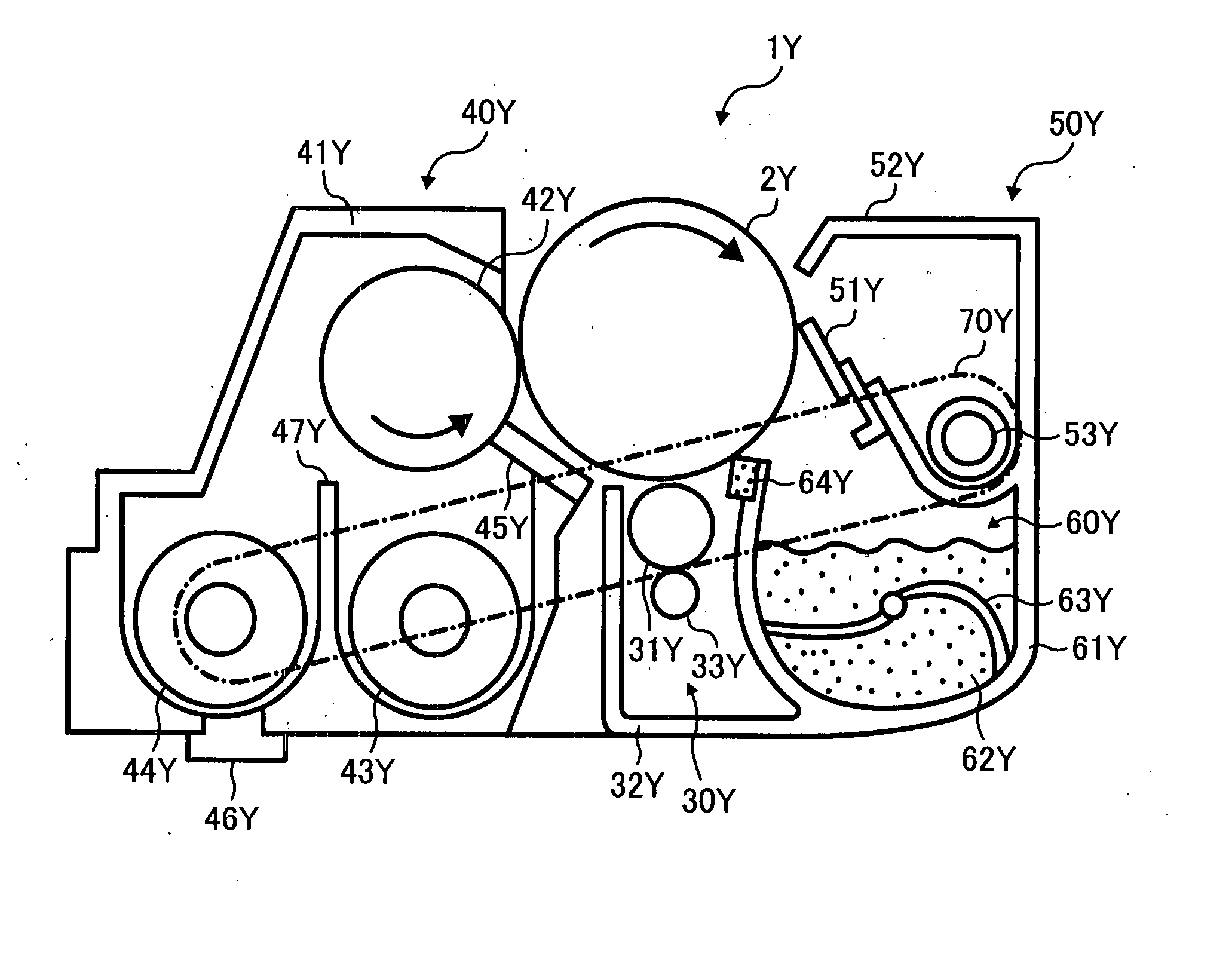
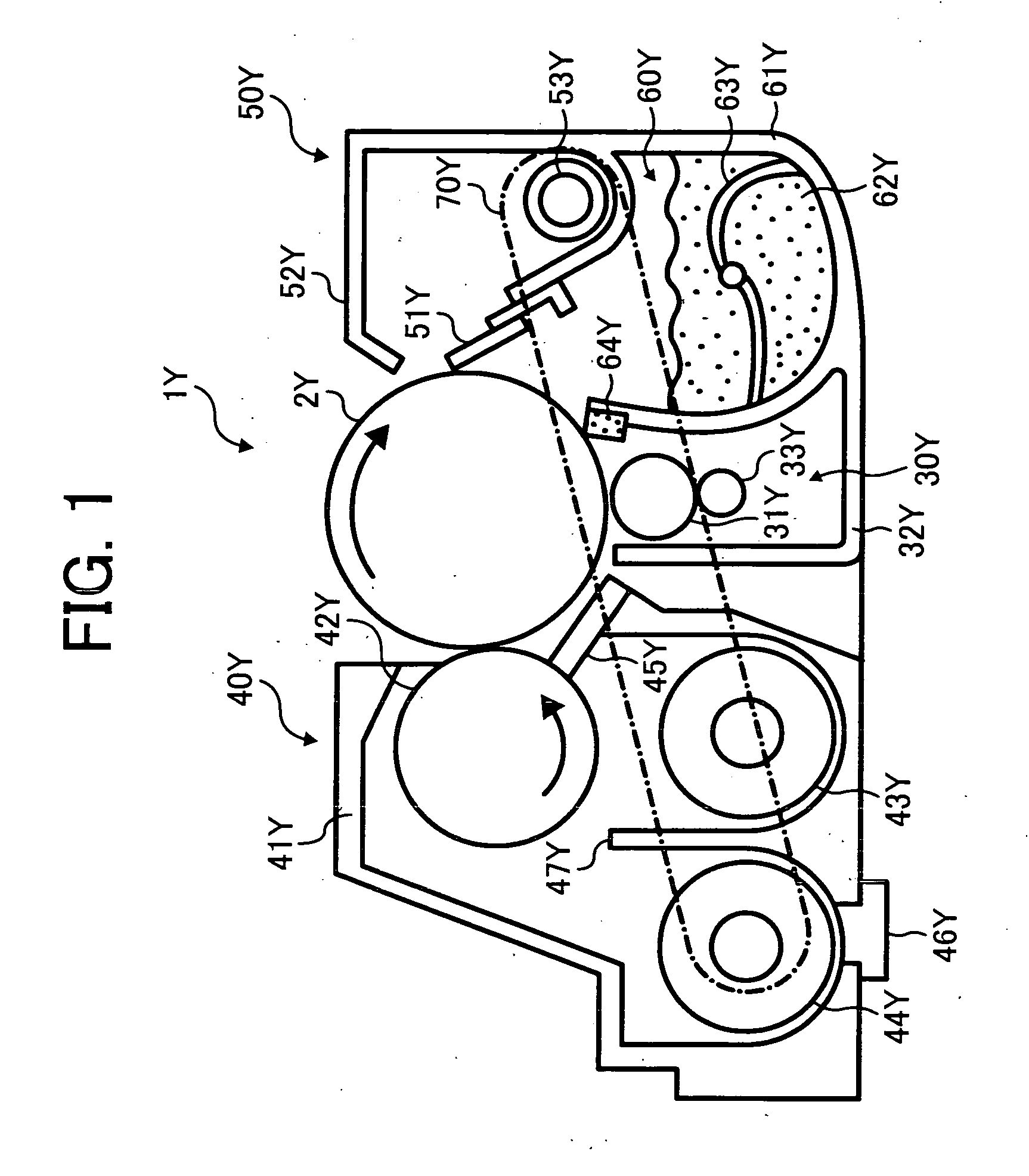
[0135] Next, a variant example of the lubricant material supplying device described in Embodiment No. 1 is described. FIG. 3 is an enlarged diagram illustrating a schematic structure of the image formation unit for yellow of the variant example.

[0136] The yellow image formation unit 1Y of the variant example has the same structure as in Embodiment No. 1 except that a brush roller 363Y functioning as the lubricant material supplying device rotates and supplies lubricant materials to the surface of the image bearing drum 2Y. A lubricant material supplying device 360Y of the variant example uses a solid lubricant material 362Y as the lubricant material. The solid lubricant material 362Y is scraped by abrasion of the brush roller 363Y and fine powdered lubricant material is obtained. This fine powdered lubricant material is attached to the brush roller 363Y. As the brush roller 363Y rotates, the attached lubricant material is conveyed to the area opposing the...

embodiment no.2

Embodiment No. 2

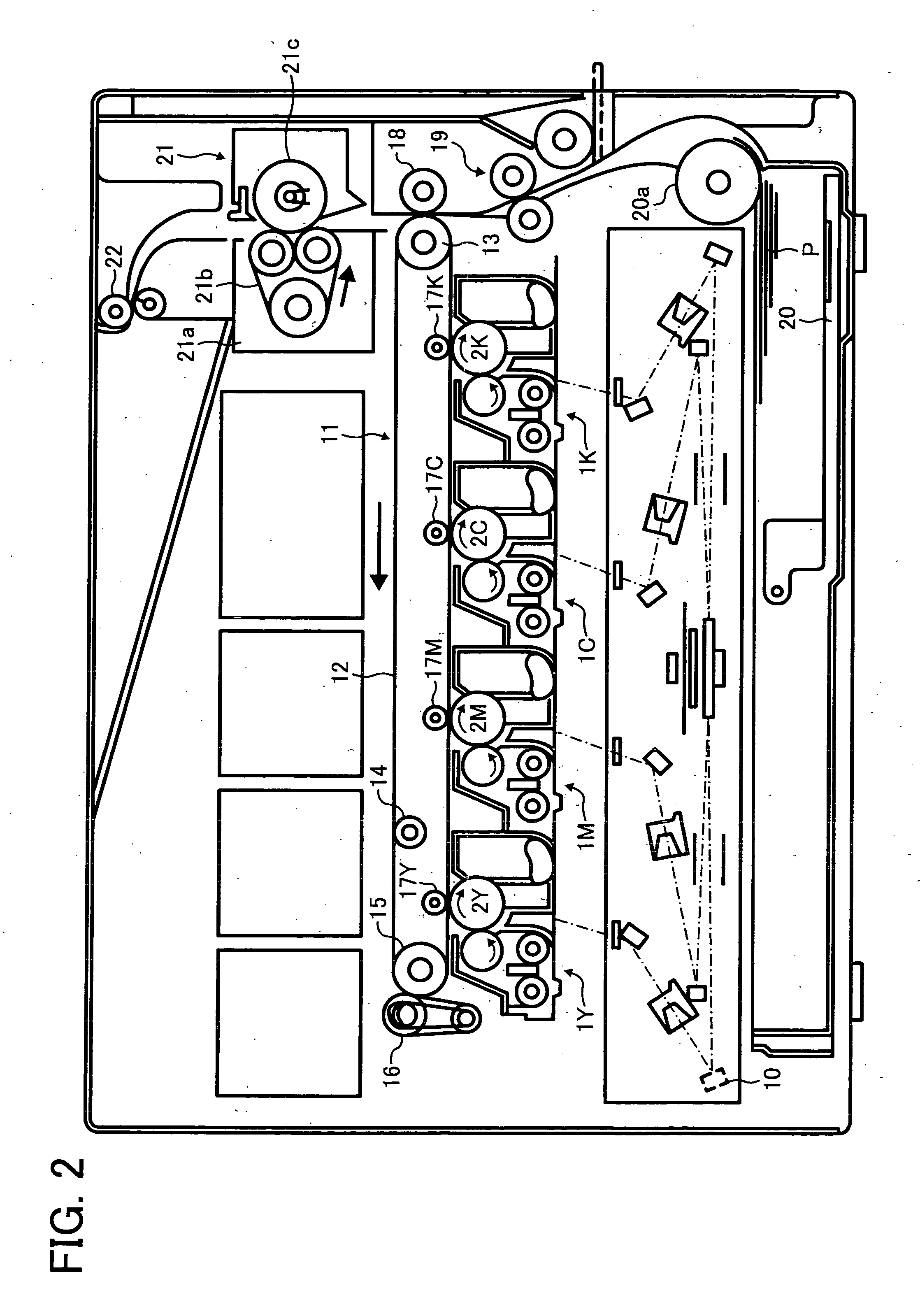
[0138] Next, as in Embodiment No. 1, another embodiment (Embodiment No. 2) in which the present invention is applied to a tandem type image forming apparatus as a printer is described. The basic structure of the printer in Embodiment No. 2 is the same as the corresponding structure of Embodiment No. 1. The same reference numerals as those in Embodiment No. 1 are used in Embodiment No. 2. Only the difference portions therebetween are described below.

[0139]FIG. 4 is a schematic structure diagram illustrating the primary portion of the printer of Embodiment No. 2. This printer adopts the same tandem system as in Embodiment No. 1. Each image formation unit 1Y, 1M, 1C and 1K is disposed perpendicularly above the intermediate transfer belt 12. This printer has a transfer medium conveying belt 118 functioning as a recording medium conveying device suspended over the secondary transfer bias roller 18 and a fixing unit 121 adopts a roller fixing system. The printer of Embodi...

example 1

[0277] An image bearing member is manufactured by applying liquids of application for an undercoating layer, a charge generating layer, a charge transport layer and a protective layer in this order to an aluminum substrate having a diameter of 60 mm.

[0278] The liquid of application for the undercoating layer is prepared as follows: Dissolve 15 parts of alkyd resin (BEKKOLITE M6401-50, manufactured by Dainippon Ink and Chemicals, Incorporated) and 10 parts of melamine resin (Super Bekkamin G-821-60, manufactured by Dainippon Ink and Chemicals, Incorporated) in 150 parts of methylethyl ketone; Add 90 parts of titanium oxide powder (Tipaque CR-EL, manufactured by Ishihara Sangyo Kaisha, Ltd.) to the resultant; and disperse the resultant with a ball mill for 12 hours.

[0279] The liquid of application for the undercoating layer is applied to the aluminum substrate by a dip coating method and dried at 130° C. for 20 minutes to obtain the undercoating layer having a thickness of 3.5 μm.

[...


PUM


Abstract

An image forming apparatus including an image bearing member having a surface free energy of not less than 45 mN/m, a charging device for charging the image bearing member, an irradiating device for irradiating the image bearing member with light to form a latent electrostatic image thereon, a developing device for developing the latent electrostatic image with a toner optionally containing a lubricant, a transfer device for transferring the developed image to a transfer medium, a cleaning device for cleaning the surface of the image bearing member, and optionally a lubricant supplying device for supplying a lubricant to the surface of the image bearing member. A lubricant is supplied to the surface of the image bearing member by at least one of the toner and the lubricant supplying device so that the surface free energy on average in an image formation area on the image bearing member is not greater than 32 mN/m while the maximum difference of the surface free energy is not greater than 5 mN/m.

Description

BACKGROUND OF THE INVENTION [0001] 1. Field of the Invention [0002] The present invention relates to an image forming apparatus and a process cartridge. [0003] 2. Discussion of the Background [0004] With the development and diffusion of home computers, the demand for improving the quality of color images produced by an electrophotographic image forming apparatus is extremely strong. There is nothing surprising for such a demand considering that materials containing color images taken by a digital camera or a scanner and half-tone colored plot areas for a graph are commonly used. [0005] In addition, images taken by a digital camera can be also commonly developed not only in silver halide photography but also by a dye sublimation printer or an inkjet printer. However, these image formations take a long time and cost of paper and ink therefore is expensive. Therefore, to make a poster and a presentation material, the speed and cost of production cause problems. [0006] The image formati...

Claims


Application Information

Patent Timeline
IPC IPC(8): G03G15/00G03G21/00
CPCG03G21/007
Inventor KABATA, TOSHIYUKISHIMOYAMA, KEISUKENAKAMORI, HIDEONOUSHO, SHINJI
Owner RICOH KK
Why Eureka
Try Eureka