Optical recording medium and process for producing the same, sputtering target, using process of optical recording medium, and optical recording apparatus

a technology of optical recording medium and optical recording apparatus, which is applied in the direction of optical recording/reproducing/erasing methods, instruments, photomechanical equipment, etc., can solve the problems of insufficient power at recording, increased noise level, and inferior recording at lower jitter

Inactive Publication Date: 2006-11-30
RICOH KK
View PDF7 Cites 7 Cited by
  • Summary
  • Abstract
  • Description
  • Claims
  • Application Information

AI Technical Summary

Benefits of technology

[0039] The inventive process for producing an optical recording medium may effectively produce optical recording media adapted to higher speed recording of 8 times or more than that of DVD.
[0040] The process for using an optical recording medium comprises conducting at least one of recording, reproducing, erasing, and rewriting of information by irradiating laser light onto the optical recording medium according to the present invention. Accordingly, the recording, reproducing, erasing, and rewrit

Problems solved by technology

In the investigations to attain the objects, the present inventors have found that excessively high melting point of recording layer materials may possibly lead to insufficient power at recording.
Further, the materials ha

Method used


Image

  • Optical recording medium and process for producing the same, sputtering target, using process of optical recording medium, and optical recording apparatus
  • Optical recording medium and process for producing the same, sputtering target, using process of optical recording medium, and optical recording apparatus
  • Optical recording medium and process for producing the same, sputtering target, using process of optical recording medium, and optical recording apparatus

Examples


example 1

—Preparation of Optical Recording Medium—

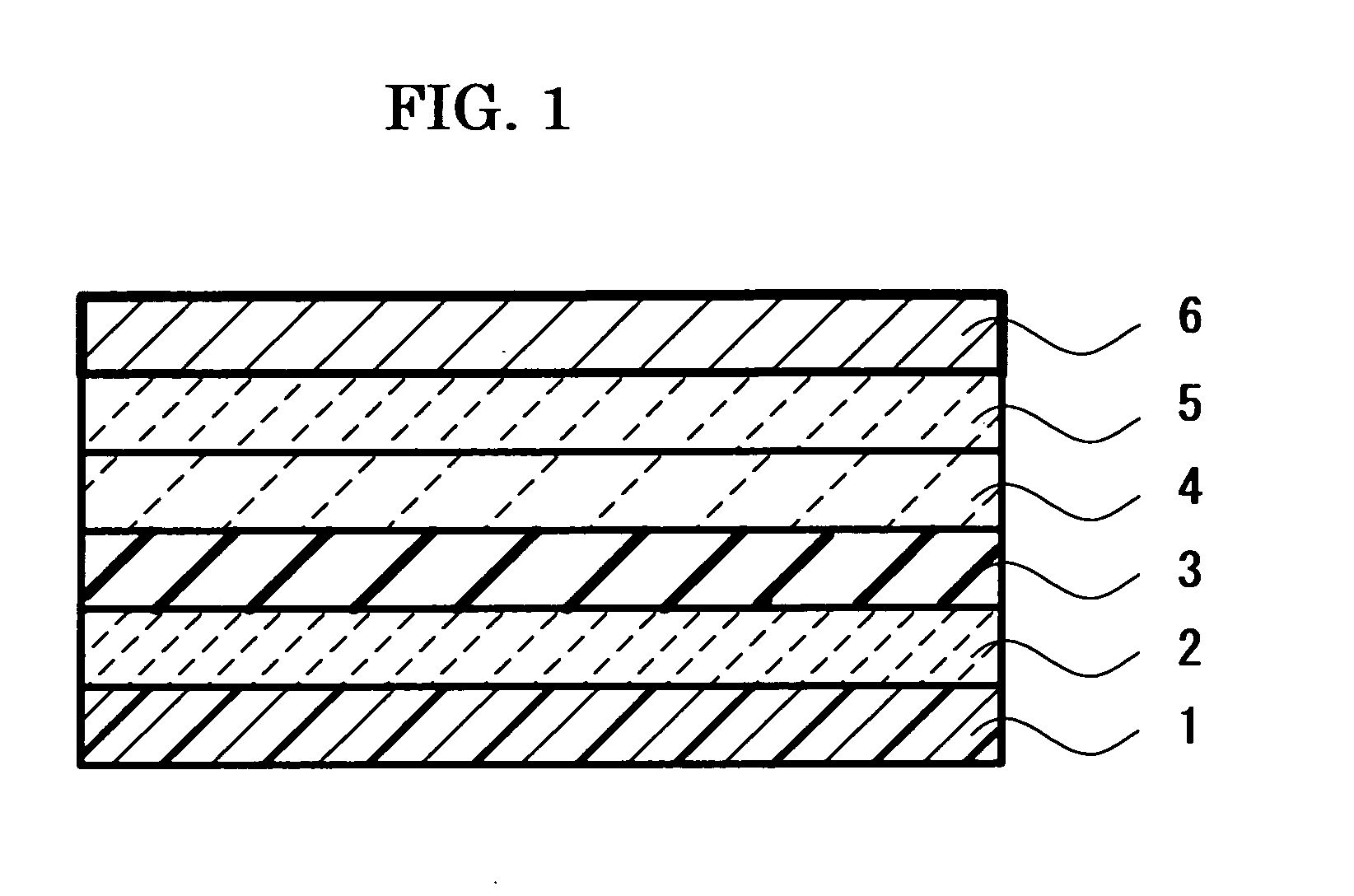
[0167] A grooved polycarbonate resin substrate of 12 cm in diameter, 0.6 mm in thickness, and 0.74 μm in track pitch was prepared. The substrate was subjected to dehydration at a high temperature.

[0168] Then, a first protective layer in 65 nm thick was formed on the substrate by means of a sputtering method using a sputtering target of which the composition was (ZnS)80(SiO2)20 as mole percent.

[0169] Then, a recording layer in 16 nm thick was formed on the first protective layer by means of a sputtering method at 3×10⁻³ torr of argon gas pressure and 300 mW of RF power using a sputtering target of which the composition was In17Sb83 as atomic percent.

[0170] Then, a second protective layer in 10 nm thick was formed on the recording layer using the sputtering target of which the composition was (ZnS)80(SiO2)20 as mole percent.

[0171] Then, a third protective layer in 4 nm thick was formed on the second protective layer using a SiC sputtering t...

example 2

—Preparation of Optical Recording Medium—

[0177] An optical recording medium of Example 2 was prepared in the same manner as Example 1, except for changing the composition of recording layer into (In0.13Sb0.87)95Ge5.

[0178] The optical recording medium was recorded in the same manner as Example 1; consequently, the linear velocity range capable of recording was as broad as 3.5 m / sec to 55 m / sec.

[0179] Further, the optical recording medium of Example 2 was evaluated as to the preservation reliability along with the recording medium of Example 1 under the condition of high temperature and high humidity, i.e. 80° C. and 85% Relative Humidity. Consequently, the recording medium of Example 1 increased 5% in the jitter property of recording mark after 300 hours, whereas the recording medium of Example 2 increased 1% or less. The results demonstrated that the addition of Ge is effective for improving the preservation reliability.

[0180] Further, it was confirmed that the addition of Ge is ...

example 3

—Preparation of Optical Recording Medium—

[0182] An optical recording medium of Example 3 was prepared in the same manner as Example 1, except for changing the composition of recording layer into (In0.12Sb0.88)90Ge5Al5.

[0183] The optical recording medium was recorded in the same manner as Example 1; consequently, the linear velocity range capable of recording was as broad as 3.5 m / sec to 58 m / sec. The linear velocity range capable of recording of Example 3 was broader than that of Example 2, which suggests that addition of Al is effective for enhancing linear velocity of recording. Further, the similar effect was also confirmed by adding Mg in place of Al.

[0184] Although the content of these elements depends on the intended linear velocity, the excessively large content may lead to mark crystallization even in reproducing light of lower power. Therefore, the content is preferably 0.15 or less as atomic ratio, i.e. 15 atomic percent or less, preferably, 0.1 or less as atomic ratio, ...


PUM

PropertyMeasurementUnit
Temperatureaaaaaaaaaa
Lengthaaaaaaaaaa

Abstract

To provide an optical recording medium and the like that is adapted to higher density and higher speed recording of 8 times or more than that of DVD (about 28 m/sec or more) and that exhibits superior repeating and reservation properties. An optical recording medium is provided that comprises a substrate, and a recording layer, wherein at least one of recording, reproducing, erasing, and rewriting of information is carried out by means of reversible phase changes at marks on the recording layer, the reversible phase changes at marks are induced between crystalline and amorphous states by laser irradiation, the length of the respective marks is 0.4 μm or less in the traveling direction of the laser irradiation, and the recording layer has a composition expressed by the formula: InαSbβ, wherein α and β are atomic percent of the respective elements; 0.73≦β/(α+β)≦0.90, α+β=100, alternatively a composition expressed by the formula: MγInαSbβ, wherein M represents an element other than In and Sb or an element combination containing two or more elements other than In and Sb; α and β are atomic percent of the respective elements, γ is atomic percent of the element or sum of atomic percent of the respective elements; 0.73≦β/(α+β)≦0.90, 0<γ<α, α+β+γ=100.

Description

CROSS-REFERENCE TO RELATED APPLICATIONS [0001] This is a continuation of Application No. PCT / JP2004 / 016899, filed on Nov. 8, 2004.BACKGROUND OF THE INVENTION [0002] 1. Field of the Invention [0003] The present invention relates to a optical recording medium capable of recording, reproducing, and rewriting information by irradiating laser to cause optical alternation on a material that constitutes a recording layer (hereinafter sometimes referring to as “phase change optical recording medium”, “optical recording medium”, “optical information recording medium” or “information recording medium”), a sputtering target for producing the optical recording medium, a process for using the recording medium, and an optical recording apparatus. [0004] 2. Description of Related Art [0005] Recently, optical recording media are demanded to address recording with higher velocity. In case of disc optical recording media in particular, the higher velocity has been practically achieved on the grounds ...

Claims


Application Information

Patent Timeline
IPC IPC(8): B32B3/02C23C14/06C23C14/08C23C14/34G11B7/006G11B7/24G11B7/243G11B7/26
CPCC23C14/06C23C14/083C23C14/3414G11B7/0062Y10T428/21G11B7/266G11B7/268G11B2007/2431G11B2007/24314G11B7/243
Inventor MIURA, HIROSHIITO, KAZUNORIHARIGAYA, MAKOTOHIBINO, EIKOSHINKAI, MASARUOHKURA, HIROKO
Owner RICOH KK
Why Eureka
Try Eureka