
System, method and arrangement which can use spectral encoding heterodyne interferometry techniques for imaging

a heterodyne interferometry and imaging technology, applied in the field of optical imaging, can solve the problems of difficult three-dimensional field of view, limited 3d field of view for such devices, and inability to achieve depth-resolved imaging having a large number of images,

Active Publication Date: 2006-11-30
THE GENERAL HOSPITAL CORP
View PDF99 Cites 19 Cited by
  • Summary
  • Abstract
  • Description
  • Claims
  • Application Information

AI Technical Summary

Benefits of technology

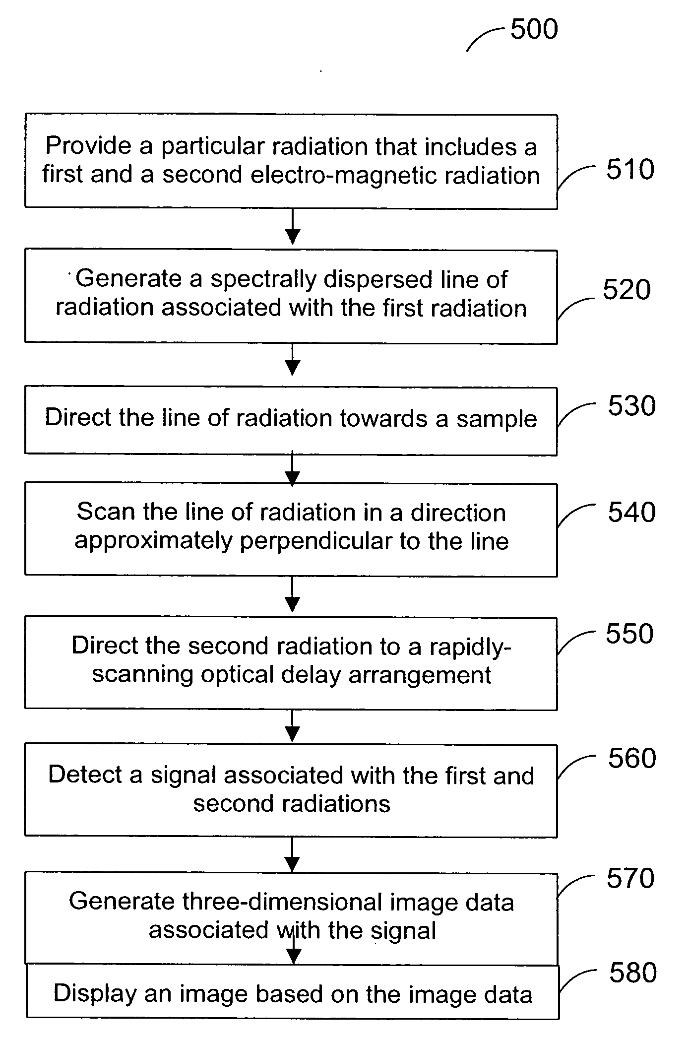
[0008] One of the objects of the present invention is to overcome certain deficiencies and shortcomings of the prior art systems (including those described herein above), and to provide exemplary SEE techniques, systems and arrangements that are capable of generating three-dimensional image data associated with a

Problems solved by technology

Achieving depth-resolved imaging having a large, three-dimensional field of view can be difficult when small diameter flexible imaging probes such as, e.g., borescopes, laparoscopes, and endoscopes are utilized.
A 3D field of view for such devices, however, may be limited to less than a few millimeters due to a small clear aperture of the objective lens and a low f-number that may be required for high-resolution optical sectioning.
These techniques may, however, require more components to construct a probe than would be required for confocal imaging that is performed using a fiber bundle.
This additional hardware can increase the size, cost, and complexity of such devices.
Scanning a reference mirror that is positioned with such accuracy over multiple discrete depths can be very difficult at the high rates required for real-time volumetric imaging.

Method used


Image

  • System, method and arrangement which can use spectral encoding heterodyne interferometry techniques for imaging
  • System, method and arrangement which can use spectral encoding heterodyne interferometry techniques for imaging
  • System, method and arrangement which can use spectral encoding heterodyne interferometry techniques for imaging

Examples


Embodiment Construction

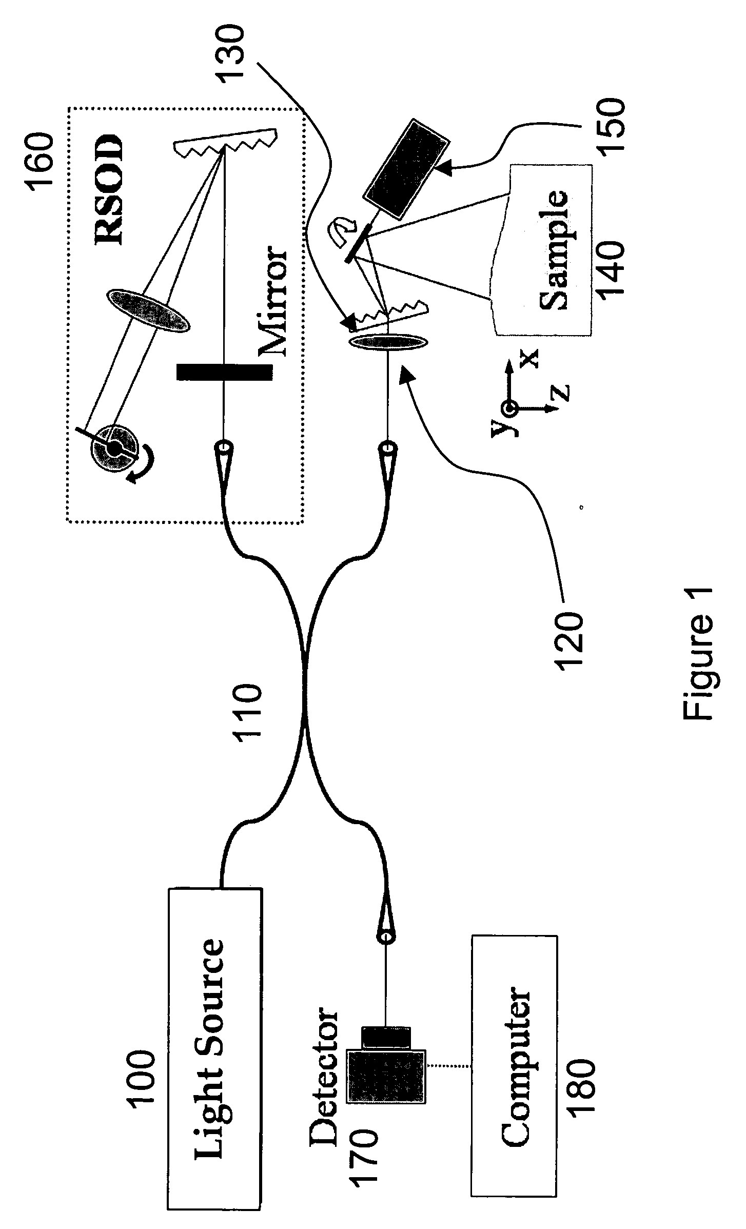
[0026] A block diagram of a system configured to acquire image data for 3D images in accordance with exemplary embodiments of the present invention is shown in FIG. 1. For example, a light source 100 or other source of electro-magnetic radiation can be provided (which may generate a light or other electro-magnetic radiation that has a broad bandwidth such as, e.g., a titanium-sapphire laser) which may be coupled to an input port of, e.g., a single-mode fiber optic 50 / 50 splitter 110 or another type of optical splitter. A compact lens-grating arrangement may be provided that can include a lens 120 (e.g., a lens having f=40 mm and a beam diameter of 0.5 mm) adapted to focus a beam of light, and a transmission grating 130 having, e.g., 1000 lines / mm (Holographix LLC) to diffract the beam and form a spectrally-encoded line (along an x-axis) on a surface of a sample 140. A galvanometric optical scanner 150 can be provided for, e.g., slow scanning of the line along a y-axis.

[0027] This e...


PUM


Abstract

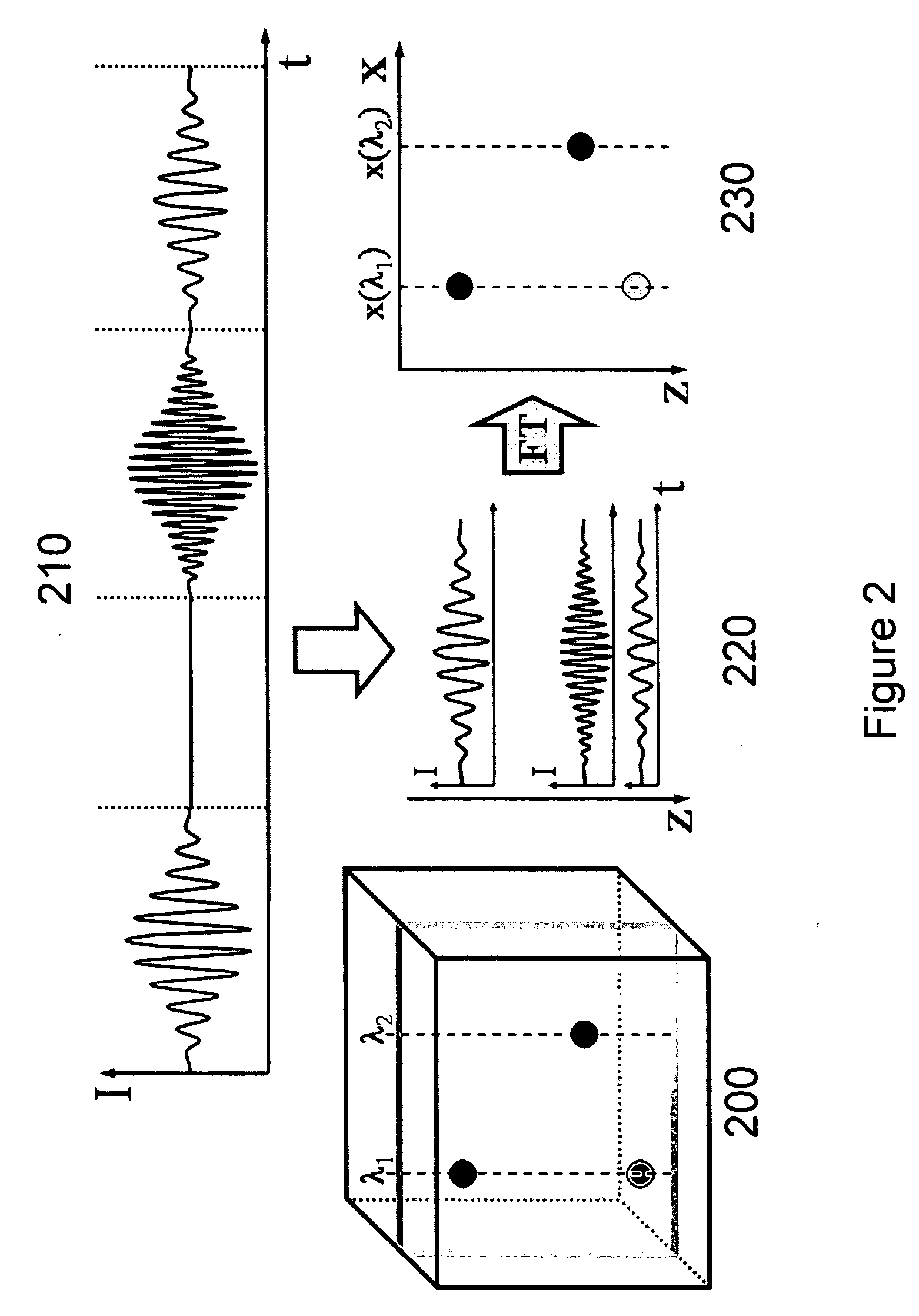
Systems, arrangements and methods for obtaining three-dimensional imaging data are provided. For example, a broadband light source can provide a particular radiation. A first electro-magnetic radiation can be focused and diffracted, and then provided to at least one sample to generate a spectrally-encoded line. A second electro-magnetic radiation may be provided to a reference, which may include a double-pass rapidly-scanning optical delay, where the first and second electro-magnetic radiations can be based on the particular radiation. An interference between a third electro-magnetic radiation (associated with the first electro-magnetic radiation) and a fourth electro-magnetic radiation (associated with the second electro-magnetic radiation) can be detected. The spectrally-encoded line may be scanned over the sample in a direction approximately perpendicular to the line. Image data containing three-dimensional information can then be obtained based on the interference. The exemplary imaging methods and systems can be used in a small fiber optic or endoscopic probe.

Description

CROSS-REFERENCE TO RELATED APPLICATION(S) [0001] This application is based upon and claims the benefit of priority from U.S. patent application Ser. No. 60 / 686,518, filed May 31, 2005, the entire disclosure of which is incorporated herein by reference.STATEMENT REGARDING FEDERALLY SPONSORED RESEARCH [0002] Development of the present invention was supported in part by the U.S. Government under National Science Foundation grant BES-0086709. Thus, the U.S. Government may have certain rights in the invention.FIELD OF THE INVENTION [0003] The present invention relates to optical imaging and, more particularly, to systems, methods and arrangements that can use spectral encoding heterodyne interferometry techniques for imaging at least one portion of a sample. BACKGROUND OF THE INVENTION [0004] Three-dimensional (“3D”) endoscopy can assist with a variety of minimally invasive procedures by providing clinicians with depth information. Achieving depth-resolved imaging having a large, three-d...

Claims


Application Information

Patent Timeline
IPC IPC(8): A61B5/05
CPCA61B5/0066G01N21/4795A61B5/7257A61B5/0084
Inventor BOUMA, BRETT EUGENETEARNEY, GUILLERMO J.YELIN, DVIRYUN, SEOK-HYUN
Owner THE GENERAL HOSPITAL CORP
Learn More