Rotatable multi-pin apparatus, and process for friction driven stitch welding and structural modification of materials

a multi-pin, rotating technology, applied in the direction of soldering apparatus, manufacturing tools, welding devices, etc., can solve the problems of reducing the frictional shear resistance of the apparatus, adhesion, wear and damage of the apparatus, and accelerating the chemical reaction between the tool material and the workpi

Inactive Publication Date: 2006-12-07
RGT UNIV OF MICHIGAN
View PDF7 Cites 18 Cited by
  • Summary
  • Abstract
  • Description
  • Claims
  • Application Information

AI Technical Summary

Problems solved by technology

This rise in temperature, an integral part of the process, also accelerates chemical reactions between tool material and the workpiece, adhesion, wear, and damage to the apparatus.
A reduction in the flow stress of the workpiece due to heating reduces the frictional shear resistance experienced by the apparatus.
Incremental advances in improving the material of construction of the conventional FSW apparatus and in improving complex procedures continue to emerge, but it is becoming increasingly evident that the current processes and apparatus for FSW are less than optimum in various ways.
Recent analytical studies show that the energy imparted from the prior art working apparatus is not used efficiently in softening the region of the workpiece, or in transferring matter across the interface, where joining is taking place, but is lost to a great extent in the surrounding material.
However, in the tail of the shear strain distribution (the edge of the elastic plastic boundary), which is a large volume of material, a substantial amount of deformation work is spent away from the tool and away from the interfaces to be joined.
Furthermore, because heat dissipation by conduction increases with increasing sectional area from the tool axis in a similar manner, loss of heat around the rotating tool occurs rapidly.
Model calculations are still evolving, but are not sufficiently focused on the problem.
Nevertheless, the weakness of the present FSW approach is obvious from the above discussion, i.e., the bulk of the workpiece material uses much of the energy imparted by the apparatus with only small fraction aiding the region to be welded.
Furthermore, FSW of high temperature alloys, such as Fe and Ni base alloys, is considerably more difficult than aluminum because, as the pin tries to “plasticize” a significant volume of the high melting alloy, excessive tool wear and reaction damage occurs at the very high temperatures generated during the process.
This leads to prematurely discarding expensive tools.
Even though exotic tool materials such as polycrystalline cubic boron nitride, W—Re alloys, and ceramic tooling are being examined by welding high temperature alloys, these expensive tool materials are easily damaged because of their brittleness and the high forces encountered in the process.

Method used


Image

  • Rotatable multi-pin apparatus, and process for friction driven stitch welding and structural modification of materials
  • Rotatable multi-pin apparatus, and process for friction driven stitch welding and structural modification of materials
  • Rotatable multi-pin apparatus, and process for friction driven stitch welding and structural modification of materials

Examples


Embodiment Construction

[0029] The disclosed device is directed to a new and efficient process for solid state joining of metals that addresses the inefficiencies in present-day FSW technology. FSW has gained considerable attention in recent years in the successful welding of aluminum alloys, but concerns exist in applying FSW to higher melting point metals because of excessive heating of the apparatus, chemical reactions, wear, and simply fracture of the expensive apparatus.

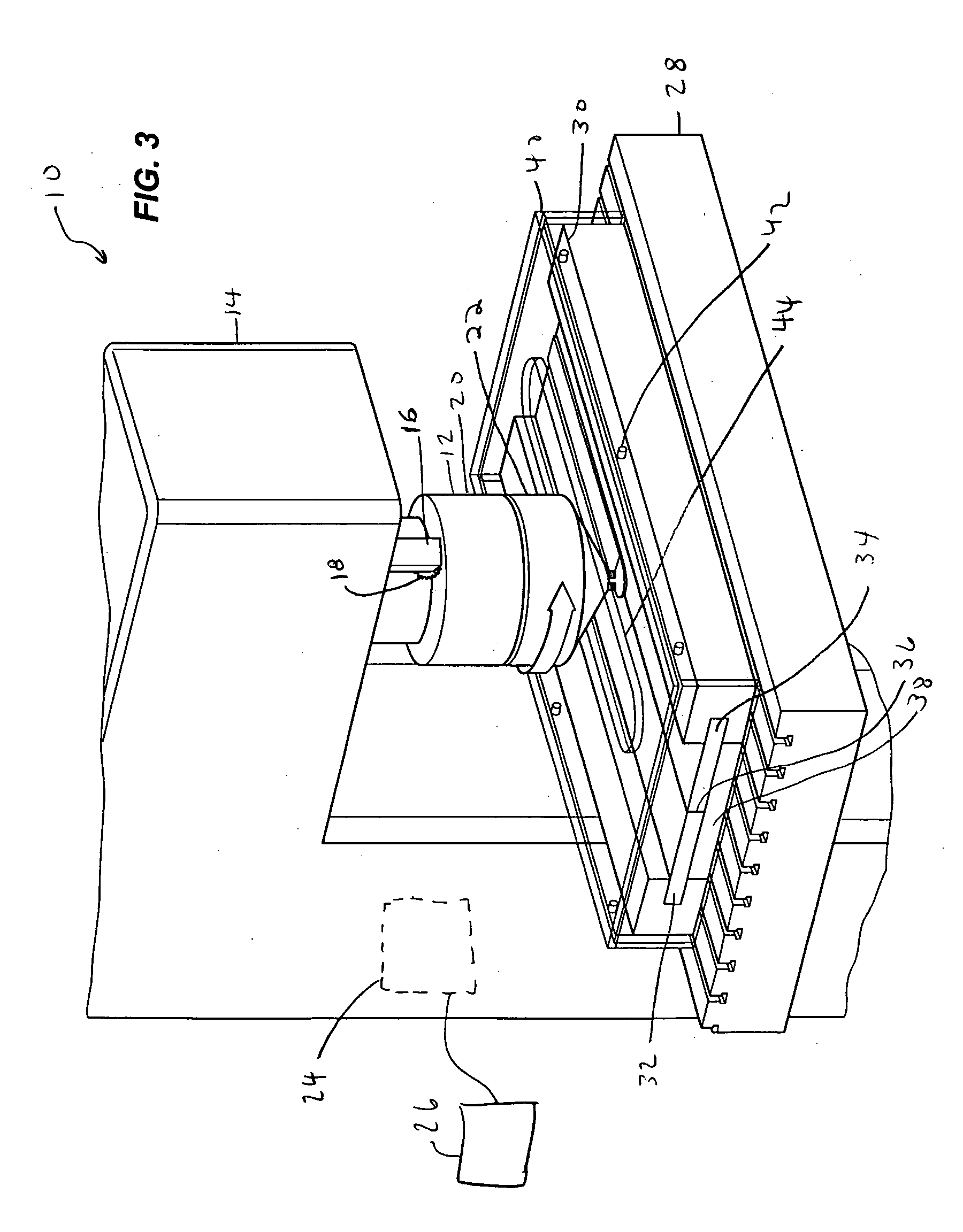
[0030] The disclosed welding device focuses the high plastic shear rate near the interface region of the workpiece undergoing joining within a narrow zone by using two or multiple rotating pins, and by defining that zone by the distance between the rotating pins of the two-pin head or a multi-pin head. Instead of relying on the size of plastic zone that develops naturally by the material's own strain hardening ability, this zone is intentionally controlled to be only a millimeter or few millimeters wide by controlling the spacing betw...


PUM

PropertyMeasurementUnit
angleaaaaaaaaaa
angleaaaaaaaaaa
angleaaaaaaaaaa

Abstract

A process is disclosed that creates a high shear rate in a workpiece using a head including a ring-shaped rotatable shoulder, a first pin and a second pin, both pins extending downwardly relative to the shoulder. The process includes coupling the workpiece to a table and rotating the first pin and the second pin in the same direction, wherein the first pin has a diameter, wherein a gap between the first pin and the second pin is less than the diameter. The head is plowed through the workpiece with the shoulder bearing downwardly against the workpiece and the first and second pin disposed in the first and second workpieces. The first pin rotates in a direction opposite the direction of the second pin in the gap to create a high shear rate of the workpiece within the gap.

Description

CROSS REFERENCE TO RELATED APPLICATIONS [0001] This application claims the benefit of U.S. Provisional Application No. 60 / 673,930, filed on Apr. 22, 2005.BACKGROUND OF THE INVENTION [0002] 1. Field of the Disclosure [0003] The present invention generally relates to processes for joining and microstructure modification of solid materials and apparatus for the same, and more particularly to a new approach to perform such tasks in a controlled manner in the solid state. [0004] 2. Description of Related Art [0005] The process of solid state joining of metals involves transfer of atoms from one side of a metal interface to the other. Solid state joining of metals has many attractive advantages over liquid metal joining processes. It is energy efficient, cleaner, free from unsafe liquid metal spurts, does not require filler metal, eliminates hazardous gas emissions, and, therefore, is environmentally more friendly. Solid state joining produces a bonded material without cast metal zone, ge...

Claims


Application Information

Patent Timeline
Patent Type & Authority Applications(United States)
IPC IPC(8): B23K20/12
CPCB23K20/125B23K20/1275B23K20/1255
Inventor GHOSH, AMIT
Owner RGT UNIV OF MICHIGAN
Why Eureka
Try Eureka