High strength induction machine, rotor, rotor cage end ring and bar joint, rotor end ring, and related methods

a high-strength induction machine technology, applied in the field of induction machines, can solve the problems of increasing the complexity of end ring design, requiring rigorous design of each major, and non-trivial centrifugal and thermal stresses, so as to achieve high strength, reduce stress, and advance the effect of operating speed and power

Inactive Publication Date: 2006-12-07
BOARD OF RGT THE UNIV OF TEXAS SYST
View PDF23 Cites 74 Cited by
  • Summary
  • Abstract
  • Description
  • Claims
  • Application Information

AI Technical Summary

Benefits of technology

[0021] Beneficially, a high strength induction machine rotor cage end ring and bar joint of embodiments of the present invention reduces stress at the common failure point of electric motors, allowing significant advancements in operating speed and power. High-speed motors produce more power than low speed motors at equivalent torque levels and can also result in the elimination of costly, complex parts such as gear transmissions. Compact, lightweight, high-speed motor designs, for example, meet the needs of advanced mobile applications, can enhance system efficiency, and can extend the capabilities of ground vehicles, remote power systems, and aerospace and defense equipment.

Problems solved by technology

Although many rotors of these induction machines have a somewhat simple and yet robust construction, as understood by those skilled in the art, for a high speed, high power density application, centrifugal and thermal stresses are non-trivial and require rigorous design of each of these major rotor components.
For example, thermally induced stresses add further complexity to end ring design, and the high power density of certain machine implies that the operating temperatures of the rotor are relatively high, even with forced air-cooling.
The temperature growth of the rotor, constructed of dissimilar metals with large differences in thermal expansion coefficients, results in high stresses at the end ring.
In addition, differential growth can occur at high-speed and / or high-temperature conditions between the rotor core and end ring components due to differing density and coefficients of thermal expansion, resulting in a high shear load on the rotor bars and bar joints.

Method used


Image

  • High strength induction machine, rotor, rotor cage end ring and bar joint, rotor end ring, and related methods
  • High strength induction machine, rotor, rotor cage end ring and bar joint, rotor end ring, and related methods
  • High strength induction machine, rotor, rotor cage end ring and bar joint, rotor end ring, and related methods

Examples


Embodiment Construction

[0049] The present invention now will be described more fully hereinafter with reference to the accompanying drawings in which embodiments of the invention are shown. This invention, however, may be embodied in many different forms and should not be construed as limited to the embodiments set forth herein; rather, these embodiments are provided so that this disclosure will be thorough and complete, and will fully convey the scope of the invention to those skilled in the art. Like numbers refer to like elements throughout.

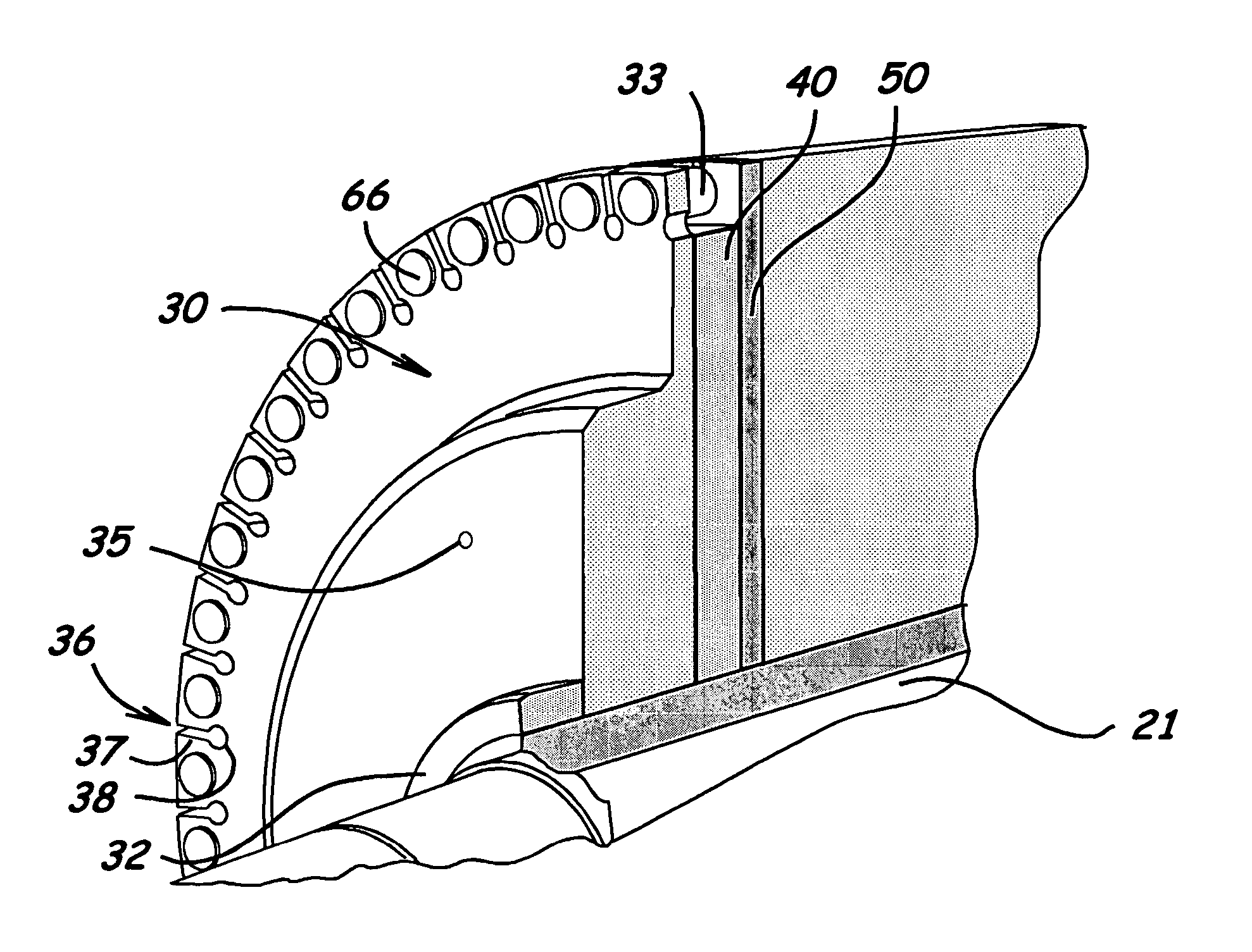
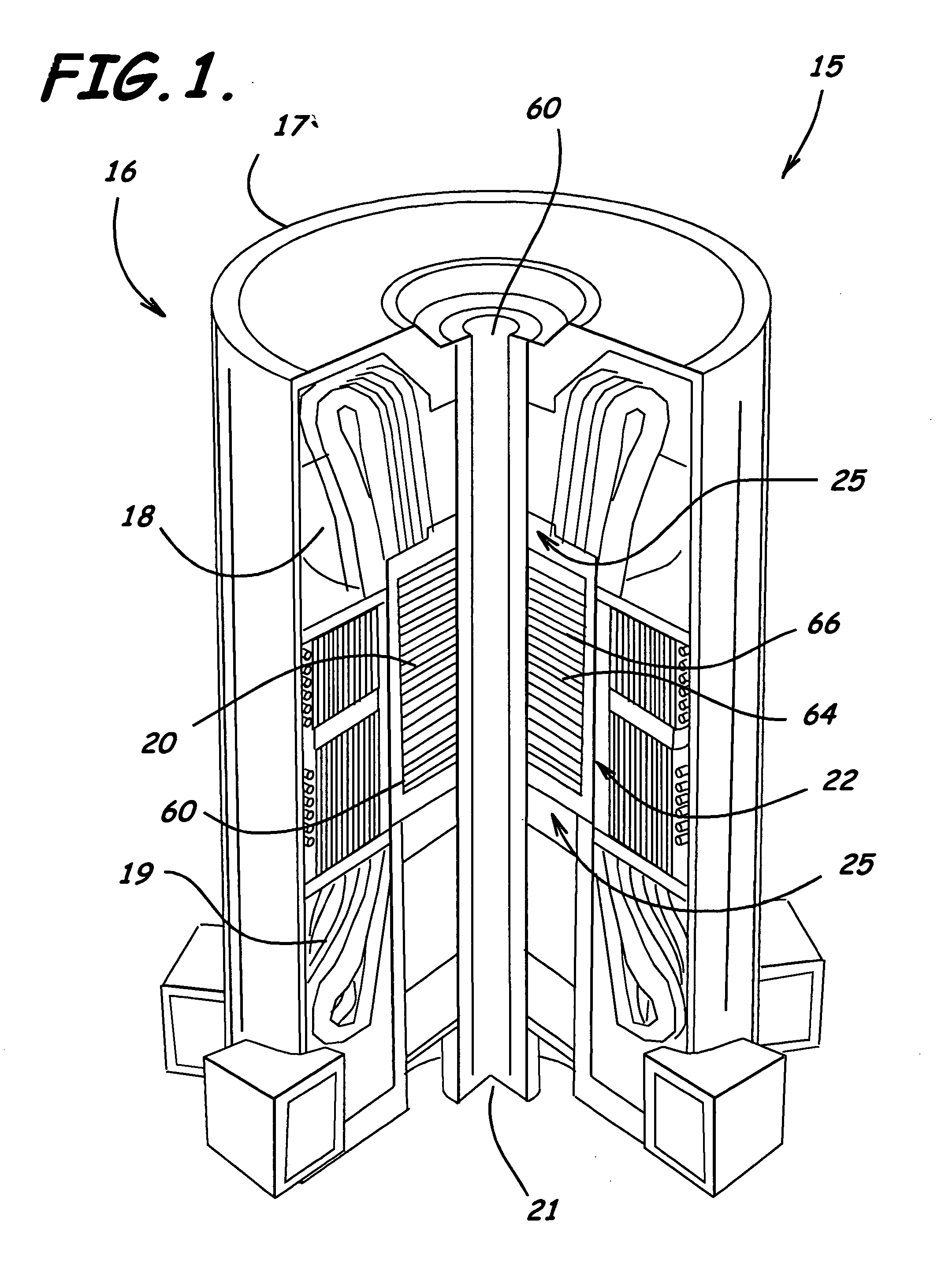
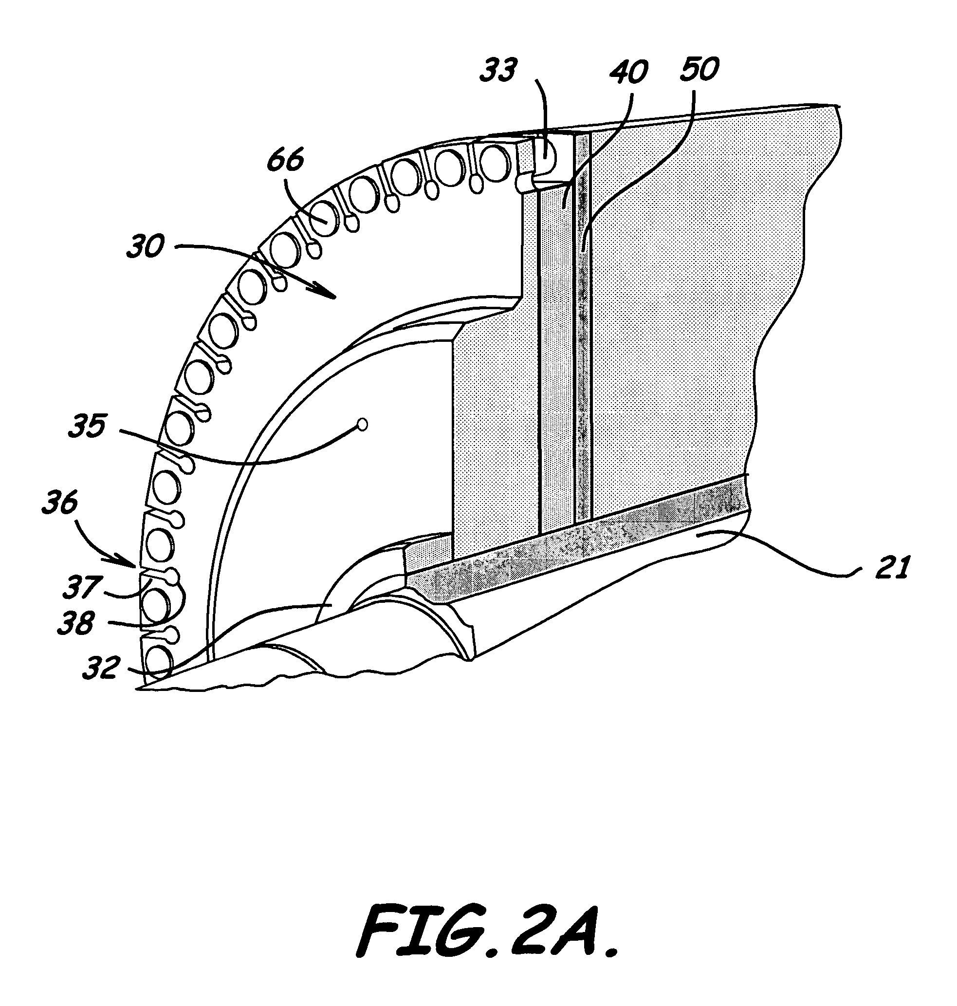
[0050]FIGS. 1-14 illustrate embodiments of an apparatus 15 such as a high strength induction machine, a rotor 20 for an induction machine, an end ring and bar joint 25 and related methods according to the present invention. As will be understood by those skilled in art, an embodiment of an apparatus 15, for example such as shown in FIGS. 1-2J, includes a stator 16 having a stator frame 17, a stator core 18 positioned in or otherwise associated with the stator frame...


PUM


Abstract

A high strength induction machine, rotor, rotor cage end ring and bar joint, rotor end ring, and related methods are provided. An embodiment of an end ring and bar joint includes a main body adapted to substantially surround a rotor shaft when mounted thereto, a plurality of slots extending inwardly in a radial direction from outer peripheries of the main body, a thicker end ring section extending outwardly from a medial portion of the main body, being thicker than the outer peripheries of the main body, and also being adapted to substantially surround the rotor shaft, and a plurality of bosses extending axially and outwardly from outer peripheral portions in a direction opposite to the thicker end ring section and each adapted to receive an end portion of a rotor bar therein.

Description

RELATED APPLICATIONS [0001] This application is related to and claims priority and benefit of U.S. Provisional Patent Application Ser. No. 60 / 647,898, filed Jan. 28, 2005, titled High Strength Induction Machine, Rotor, Rotor Cage End Ring and Bar Joint, Rotor End Ring, and Related Methods, by inventors Matthew Caprio, Vasileios Lelos, John Herbst, Stephen Manifold, and Howard Jordan, and which is incorporated herein by reference in its entirety.GOVERNMENT INTEREST [0002] 2. Reference to Government Funding [0003] The United States Government has rights in this invention pursuant to Contract No. DTRF53-99-H-00006 between the Federal Railroad Administration and the University of Texas at Austin.BACKGROUND OF THE INVENTION [0004] 1. Field of the Invention [0005] The present invention relates to induction machines and, more particularly, to end ring and bar joints associated with such motors and generators and related methods. [0006] 2. Description of Related Art [0007] Over the years va...

Claims


Application Information

Patent Timeline
Patent Type & Authority Applications(United States)
IPC IPC(8): H02K17/00
CPCH02K17/165
Inventor CAPRIO, MATTHEW T.LELOS, VASILEIOSHERBST, JOHNMANIFOLD, STEPHENJORDON, HOWARD
Owner BOARD OF RGT THE UNIV OF TEXAS SYST
Why Eureka
Try Eureka