Ionosphere delay measurement using carrier phase

a carrier phase and ionosphere technology, applied in the direction of plural information simultaneous broadcast, instruments, polarisation/directional diversity, etc., can solve the problem that single frequency band receivers cannot take advantage of the dispersive nature of the ionosphere and the relative small range error

Active Publication Date: 2006-12-07
L3 TECH INC
View PDF20 Cites 17 Cited by
  • Summary
  • Abstract
  • Description
  • Claims
  • Application Information

AI Technical Summary

Benefits of technology

[0011] In one embodiment, hardware and software for ionospheric measurements are based on a single-band of a receiver by comparing the phase of upper and lower modulation sidebands. In one embodiment, a receiver provides improved quality, redundancy, resistance to spoofing, and / or resistance to jamming by making separate ionospheric measurements by comparing upper and lower modulation sidebands from signals transmitted using carriers in different frequency bands. In one embodiment, a GPS receiver provides ionospheric measurements by comparing the phase relationship between an upper modulation sideband and a lower modulation sideband of the L1 signal, and by separately comparing an upper modulation sideband and a lower modulation sideband of the L2 signal. This provides two relatively independent measurements for each satellite.
[0013] In one embodiment, relative phase measurement obtained by comparing the phase of an upper modulation sideband and a lower modulation sideband, is used to assist in resolving the phase ambiguity.

Problems solved by technology

In the case of satellite navigation systems, such as, for example, the Global Positioning System (GPS), bending of the signal propagation path causes a relatively small range error, particularly if the satellite elevation angle is greater than 50 degrees.
However, the change in the propagation speed causes a significant range error, and therefore should be accounted for.
As the ionosphere is a dispersive medium, it causes a delay that is frequency dependent.
Single frequency band receivers cannot take advantage of the dispersive nature of the ionosphere.

Method used


Image

  • Ionosphere delay measurement using carrier phase
  • Ionosphere delay measurement using carrier phase
  • Ionosphere delay measurement using carrier phase

Examples


Embodiment Construction

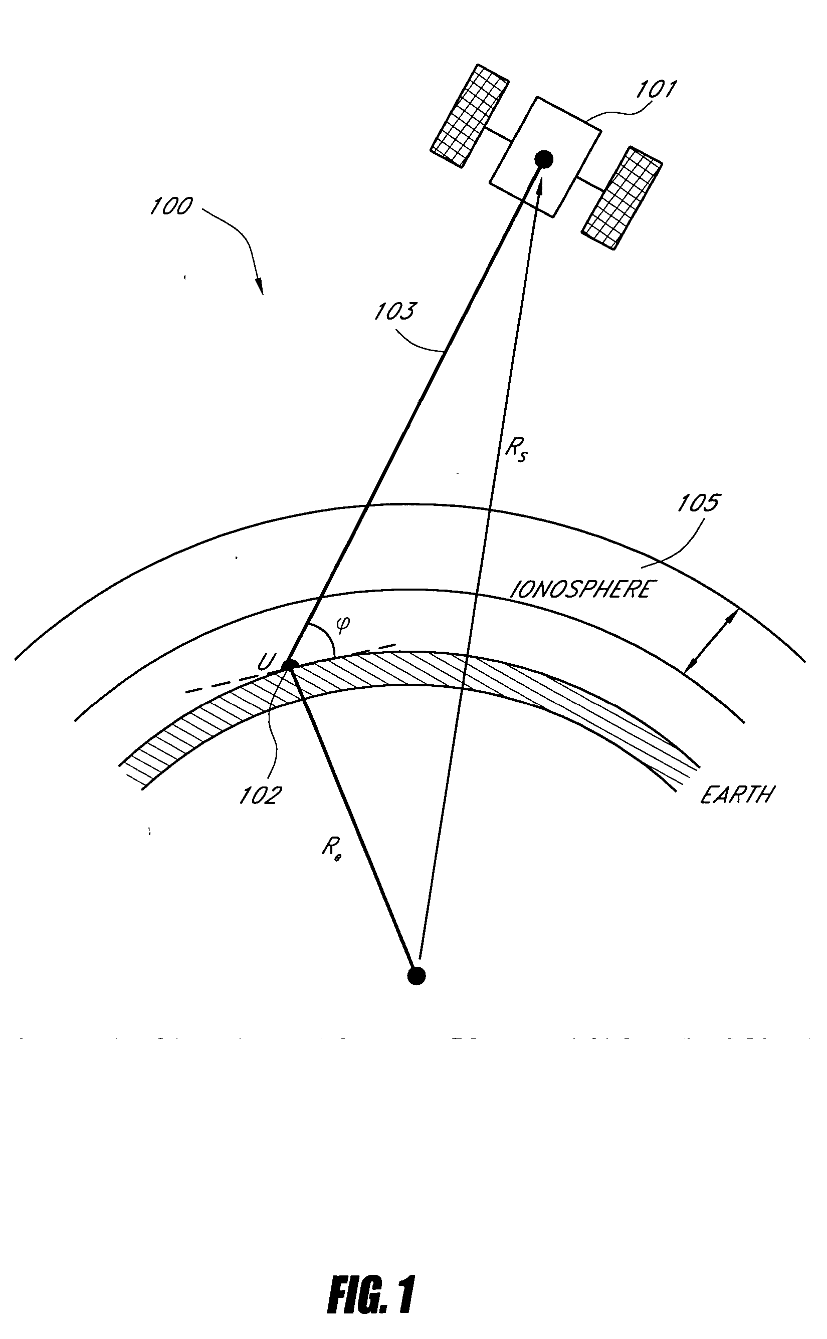
[0026]FIG. 1 shows propagation of signals from a satellite 101 along a propagation path 103 to a receiver 102. A portion of the propagation path 103 passes through the ionosphere 105.

[0027] The ionosphere 105 is a dispersive medium, which means the path taken by the radio frequency signal is frequency dependant. Additionally, the speed at which the radio frequency travels through the ionosphere is also frequency dependant. As a result of these effects, the radio frequency bends along the trajectory from the satellite 101 and changes its group and wave velocity as the radio frequency signals propagate along the path 103 through the ionospheric layers to reach the receiver 102. In the case of satellite navigation systems, such as, for example, the Global Positioning System (GPS), bending of the signal propagation path 103 causes a relatively small range error, particularly if the satellite 101 elevation angle φ is sufficiently large. However, the change in the propagation speed cause...


PUM


Abstract

One or more atmospheric propagation effects are estimated by using a phase comparison between and upper sideband and a lower sideband of a modulated signal. In one embodiment, one or more propagation effects are estimated by using a phase comparison between an upper sideband and a lower sideband of a satellite navigation signal. In one embodiment, one or more ionospheric propagation effects are estimated by using a phase comparison between an upper sideband and a lower sideband of a GPS M-code signal.

Description

BACKGROUND [0001] 1. Field of the Invention [0002] The present invention relates to measurement of ionospheric propagation effects on Radio Frequency (RF) signals by comparing carrier phase between signals of different frequency, such as, for example, upper and lower sidebands of a GPS M-code signal. [0003] 2. Description of the Related Art [0004] In the upper regions of the earth's atmosphere, ultraviolet and X-ray radiation coming from the sun interact with the atmospheric gas molecules and atoms. These interactions result in ionization giving rise to large numbers of free “negatively charged” electrons and “positively charged” atoms and molecules. The region of the atmosphere where gas ionization takes place is called the ionosphere. It extends from an altitude of approximately 50 km to about 1,000 km or higher (the upper limit of the ionospheric region is not clearly defined). [0005] The electron density within the ionosphere is not constant. It changes with time and altitude. T...

Claims


Application Information

Patent Timeline
Patent Type & Authority Applications(United States)
IPC IPC(8): G01S5/14G01S19/22
CPCG01S19/37G01S19/32
Inventor WATSON, GEORGEGRAHAM, SCOTTREED, CHRIS
Owner L3 TECH INC
Why Eureka
Try Eureka