

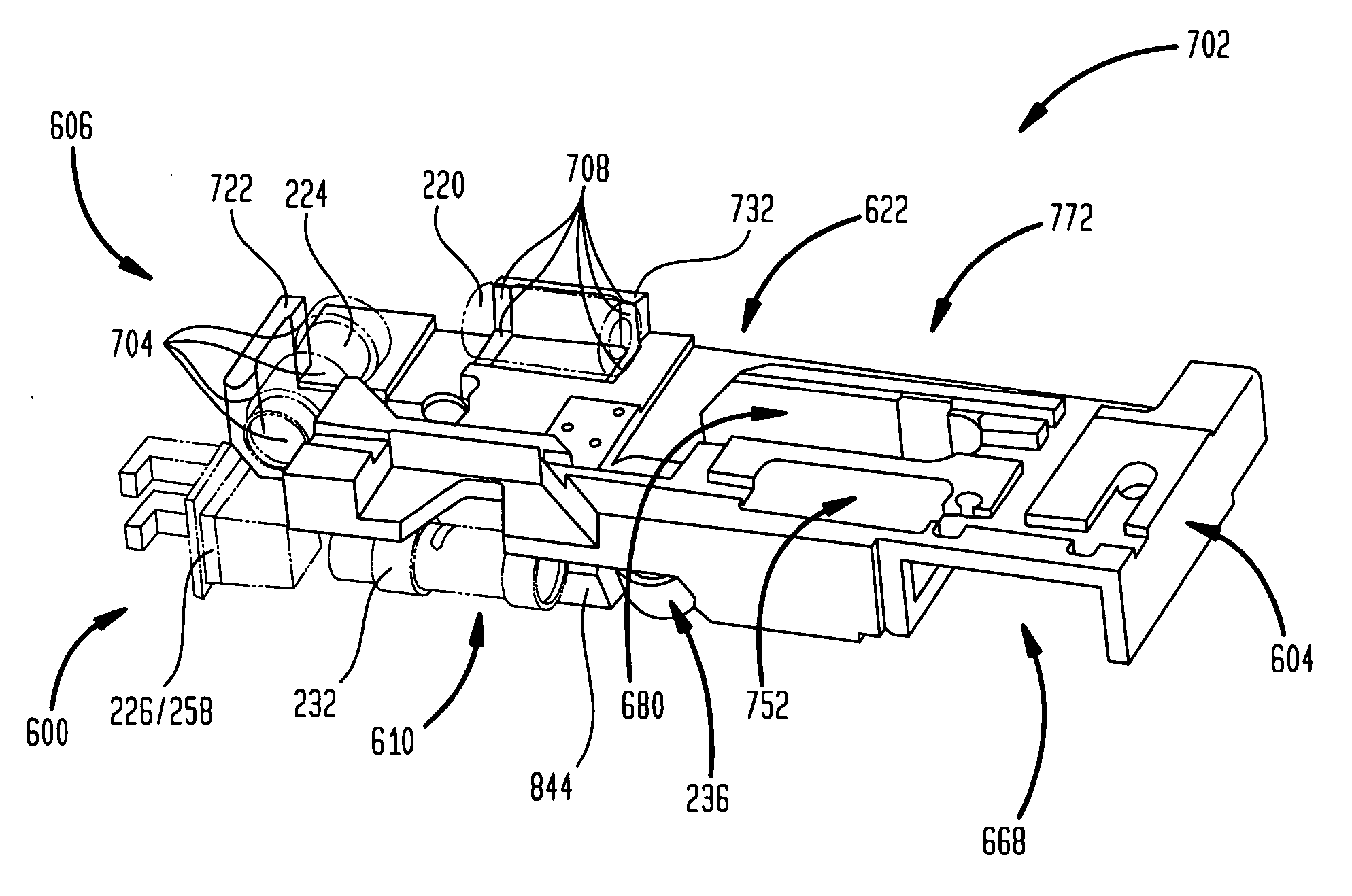
Holographic drive head and component alignment
a holographic drive and component technology, applied in the field of holographic drive head and component alignment, can solve the problems of difficult and time-consuming, meticulous alignment of the many components and elements of the holographic drive head assembly, and the use of such large optical breadboards may be impractical for commercial holographic storage systems, so as to reduce reflections
- Summary
- Abstract
- Description
- Claims
- Application Information
AI Technical Summary
Benefits of technology
Problems solved by technology
Method used
Image

Examples
Embodiment Construction
[0066] It is advantageous to define several terms before describing the invention. It should be appreciated that the following definitions are used throughout this application.
Definitions
[0067] Where the definition of terms departs from the commonly used meaning of the term, applicant intends to utilize the definitions provided below, unless specifically indicated.
[0068] For the purposes of the present invention, directional terms such as “top”, “bottom”, “above”, “below”, “left”, “right”, “horizontal”, “vertical”, etc. are merely used for convenience in describing the various embodiments of the present invention. The embodiments of the present invention may be oriented in various ways. For example, the embodiments shown in FIGS. 3 through 12 may be flipped over, rotated by 90° in any direction, etc.
[0069] For the purposes of the present invention, the term “laser” refers to conventional lasers, as well as laser diodes (LDs).
[0070] For the purposes of the present invention, th...
PUM
 Abstract
Description
Claims
Application Information