
Sheet for manufacturing optical disk and optical disk

a technology for optical discs and manufacturing sheets, applied in the direction of instruments, mechanical record carriers, data recording, etc., can solve the problems of discs liable to data reproduction and recording errors, difficult to form uniform protective layers, irregular thicknesses in adhesive layers, etc., and achieve uniform thickness

Inactive Publication Date: 2006-12-14
LINTEC CORP
View PDF9 Cites 8 Cited by
  • Summary
  • Abstract
  • Description
  • Claims
  • Application Information

AI Technical Summary

Benefits of technology

The present invention provides an optical disc manufacturing sheet and optical disc that have uniform thickness of the adhesive layer and are resistant to pressure imprint. The optical disc manufacturing sheet has a curable adhesive layer with a pre-curing storage elastic modulus of 103 to 106 Pa and a post-curing storage elastic modulus of 107 to 1011 Pa. The adhesive layer contains an energy rays-curable polymer material, which is preferably an acrylic ester copolymer having energy rays-curable groups in the side chains thereof. The optical disc manufacturing sheet can be used to adhere a protective layer to the recording layer of an optical disc. The resulting optical disc is resistant to pressure imprint without causing warpage or other problems.

Problems solved by technology

However, with such methods it is difficult to form a protective layer of a uniform thickness, and the resulting discs are liable to data reproduction and recording errors particularly if they are large-capacity optical discs.
However, even in this method the application method produces thickness irregularities in the adhesive layer, which may not have the uniform thickness required by the product.
However, the problem is that because conventionally used pressure sensitive adhesives have low elastic modulus in the room temperature range, when pressure is applied to part of the cover film the cover film is deformed together with the pressure sensitive adhesive layer.
Such pressure imprint on a cover film is a serious problem, interfering with data recording and reproduction especially in the case of Blu-ray Discs, which use high numerical aperture (0.85) lenses and short wavelength (405 nm) lasers to increase recording densities.
Although current Blu-ray Discs are enclosed in cartridges, it is likely that they will be made bare in the future, at which time the problems mentioned above would be noticed.

Method used


Image

  • Sheet for manufacturing optical disk and optical disk
  • Sheet for manufacturing optical disk and optical disk
  • Sheet for manufacturing optical disk and optical disk

Examples


first embodiment

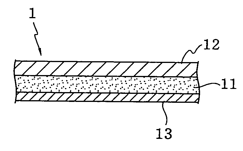
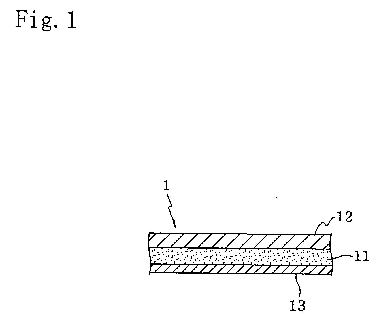
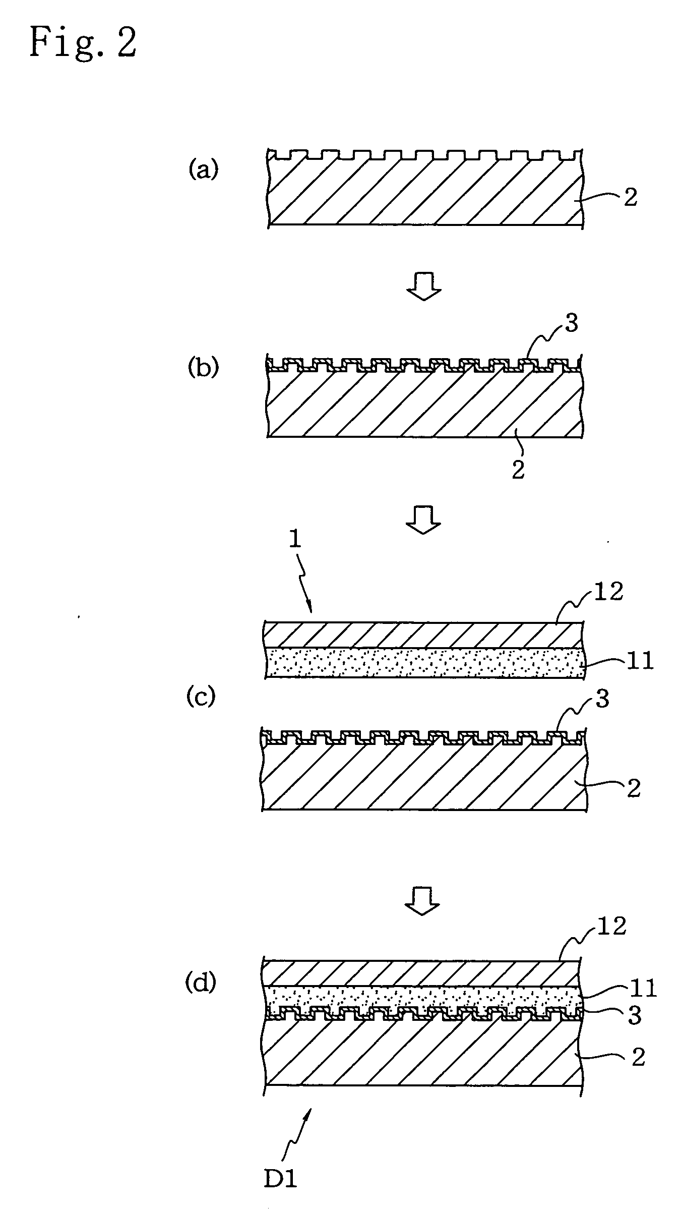
[0020]FIG. 1 is a cross-section of an optical disc manufacturing sheet according to a first embodiment of the present invention, while FIGS. 2(a) through 2(d) are cross-sections illustrating one example of an optical disc manufacturing method using an optical disc manufacturing sheet according to this embodiment, and FIG. 3(a) through 3(f) are cross-sections illustrating another example of an optical disc manufacturing method using an optical disc manufacturing sheet according to this embodiment.

[0021] As shown in FIG. 1, optical disc manufacturing sheet 1 of this embodiment consists of adhesive layer 11, protective sheet 12 which is laminated on one surface (upper surface in FIG. 1) of adhesive layer 11, and release sheet 13 which is laminated on the other surface (lower surface in FIG. 1) of adhesive layer 11. Protective sheet 12 becomes the protective layer of an optical disc, and release sheet 13 is peeled off when optical disc manufacturing sheet 1 is used.

[0022] The purpose ...

second embodiment

[0085]FIG. 4 is a cross-section showing an optical disc manufacturing sheet according to the second embodiment of the present invention, while FIGS. 5(a) through 5(e) are cross-sections illustrating one example of the method for manufacturing an optical disc using an optical disc manufacturing sheet according to this embodiment.

[0086] As shown in FIG. 4, optical disc manufacturing sheet 1′ of this embodiment consists of adhesive layer 11 and release sheets 13 and 13′ which are laminated on either side of adhesive layer 11. Release sheets 13 and 13′ are peeled off when optical disc manufacturing sheet 1 is used.

[0087] Adhesive layer 11 is made of a material similar to that of adhesive layer 11 of optical disc manufacturing sheet 1 of the aforementioned first embodiment, and has a similar thickness. Moreover, release sheets 13 and 13′ may be similar to release sheet 13 of optical disc manufacturing sheet 1 of the aforementioned first embodiment. However, preferably one of release sh...

example 1

[0097] n-butylacrylate and acrylic acid were polymerized at a mole ratio of 69.22:30.78 in ethyl acetate to obtain an acrylic copolymer (a1) solution (solids concentration 30% by weight).

[0098] Methacryloyloxyethyl isocyanate was added as an unsaturated group-containing compound (a2) to the aforementioned acrylic copolymer solution, and the isocyanate groups of the methacryloyloxyethyl isocyanate were reacted with the carboxyl groups of the acrylic copolymer to obtain an energy rays-curable acrylic ester copolymer (A) with a mean side-chain introduction rate of 9.24 mol % of the methacryloyl groups which are the energy rays-curable groups and a weight-average molecular weight (Mw) of 680,000.

[0099] 5 parts by weight of 2,2-dimethoxy-1,2-diphenylethane-1-one as the photopolymerization initiator and 1.7 parts by weight of an isocyanate type crosslinking agent (manufactured by NIPPON POLYURETHANE INDUSTRY CO., LTD., Coronate L) as the crosslinking agent were added per 100 parts by we...


PUM

PropertyMeasurementUnit
elastic modulusaaaaaaaaaa
storage elastic modulusaaaaaaaaaa

Abstract

Optical disc manufacturing sheet 1 comprising protective sheet 12 and curable adhesive layer 11 with a pre-curing storage elastic modulus of 103 to 106 Pa and a post-curing storage elastic modulus of 107 to 1011 Pa is laminated on reflective layer 3 formed on optical disc substrate 2. In the optical disc D1 obtained in this way, adhesive layer 11 has a uniform thickness and protective sheet 12 is resistant to pressure imprint.

Description

TECHNICAL FIELD [0001] The present invention relates to an optical disc manufacturing sheet and optical disc, and more particularly to an optical disc manufacturing sheet and optical disc which are resistant to pressure imprint. BACKGROUND ART [0002] To protect the recording layer of optical discs, ultraviolet-curable resins are often applied by spin coating or the like to the recording layer surfaces and cured to form an optically transparent protective layer. However, with such methods it is difficult to form a protective layer of a uniform thickness, and the resulting discs are liable to data reproduction and recording errors particularly if they are large-capacity optical discs. [0003] A method has therefore been proposed wherein an ultraviolet-curable liquid adhesive is applied by spin coating or the like to the recording layer surface, an optically transparent cover film is laminated to the resulting adhesive layer, and the ultraviolet-curable adhesive is then cured. However, ...

Claims


Application Information

Patent Timeline
Patent Type & Authority Applications(United States)
IPC IPC(8): G11B3/70G11B7/24G11B7/254G11B7/256G11B7/257G11B7/26
CPCG11B7/263G11B7/256G11B7/26
Inventor KATOH, KAZUYAKUBOTA, SHINMIYATA, SOU
Owner LINTEC CORP
Learn More