Tunable dispersion compensator and method of manufacturing the same

a technology of tunable dispersion compensator and compensator, which is applied in the direction of multiplex communication, instruments, optical elements, etc., can solve the problems of increased connection wirings of respective heater elements, inability to ensure sufficient transmission quality, and change in length of optical fiber transmission lines, etc., to achieve the effect of reducing the cost and being convenient to constru

Active Publication Date: 2006-12-14
MITSUBISHI ELECTRIC CORP
View PDF5 Cites 7 Cited by
  • Summary
  • Abstract
  • Description
  • Claims
  • Application Information

AI Technical Summary

Benefits of technology

[0012] The present invention has been made to solve the above-mentioned problems. An object of the present invention is to obtain a tunable dispersion compensator in which a heater portion can be easily formed to reduce a cost thereof. Another object of the present invention is to obtain a tunable dispersion compensator in which the number of heater elements virtually increases without an increase in the number of connection wirings for the heater elements, thereby obtaining a group delay time characteristic identical to that in the case where the number of heater elements increases. Another object of the present invention is to obtain a tunable dispersion compensator in which a temperature gradient can be applied to a grating without an increase in power consumption, thereby shortening a response time of a dispersion change. Another object of the present invention is to provide a method of manufacturing each of the tunable dispersion compensators.
[0014] According to the present invention, it is possible to provide the tunable dispersion compensator in which the heater portion can be easily constructed to reduce a cost thereof.

Problems solved by technology

A problem which occurs at this time is a change in length of an optical fiber transmission line which is caused by path switching.
Therefore, when the change in length which is caused by the path switching becomes 5.9 km or more, the waveform of the optical signal is distorted by the chromatic dispersion of the optical fiber, with the result that sufficient transmission quality cannot be ensured.
However, when the number of heater elements increases, there is a problem in that the number of connection wirings for the respective heater elements becomes larger and thus it is difficult to mount the heater elements.
The heater element interval is a small interval of 5 μm, so there is a problem in that an advanced manufacturing technique is required and it is difficult to reduce a cost of the substrate (heater substrate) on which the heater elements are formed.
However, much of heat applied to the thin film heaters flows to the heat spreader side, so that there is a problem in that the power consumption becomes larger.
Therefore, there is a problem in that the predetermined temperature gradient of 50° C. cannot be applied to the grating.

Method used


Image

  • Tunable dispersion compensator and method of manufacturing the same
  • Tunable dispersion compensator and method of manufacturing the same
  • Tunable dispersion compensator and method of manufacturing the same

Examples


embodiment 1

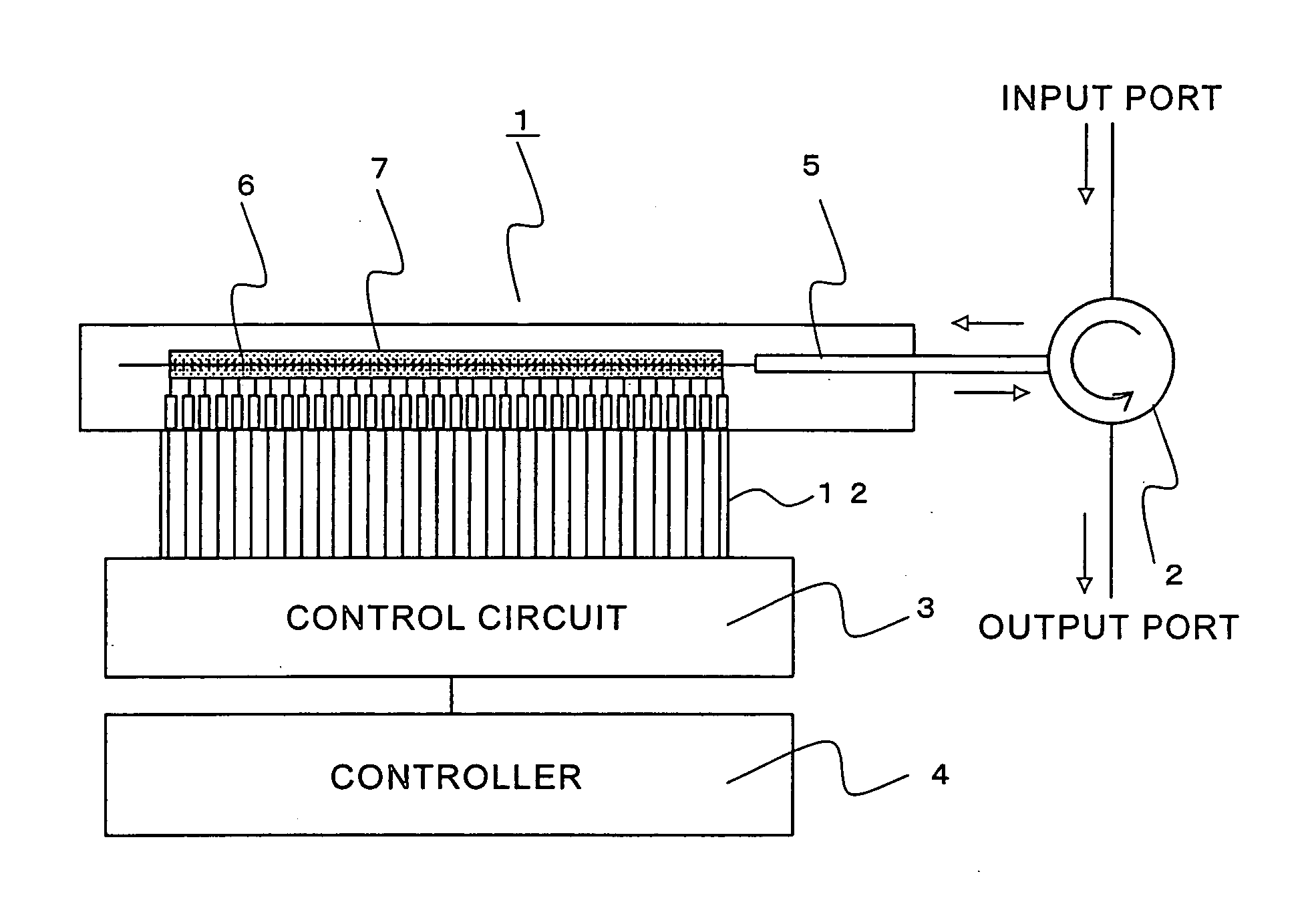
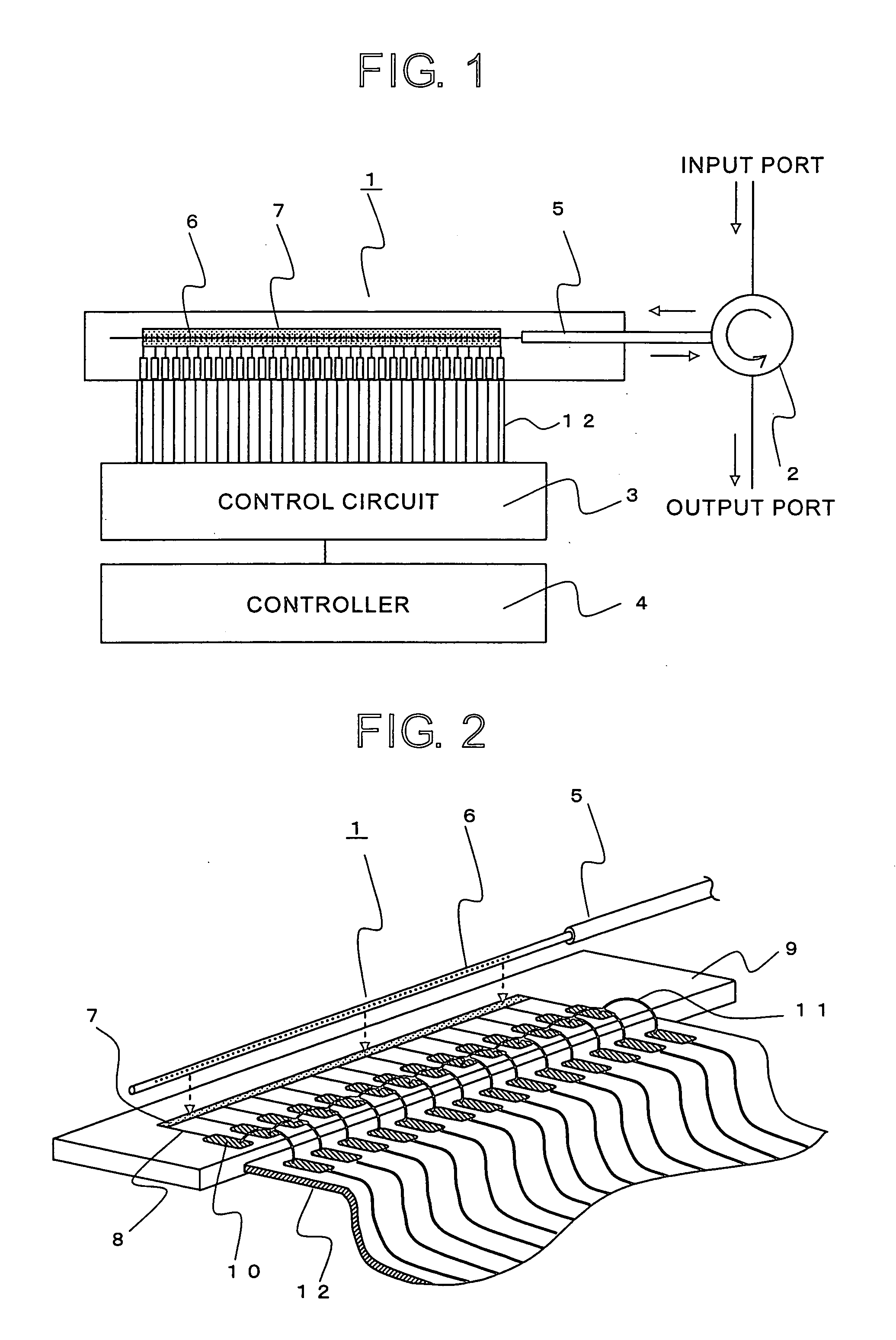
[0054]FIG. 1 is a structural diagram showing an example of a structure of a tunable dispersion compensator according to Embodiment 1 of the present invention. The tunable dispersion compensator fundamentally includes a fiber grating unit 1, a circulator 2, a control circuit 3, and a controller 4. The fiber grating unit 1 is fixed to a substrate or the like such that a thin film heater 7 serving as a heating means for heating a fiber grating 6 (grating portion) is formed in a portion of an optical fiber 5 is extended along the fiber grating 6. The circulator 2 is provided on an input and output side of the optical fiber 5. The thin film heater 7 serving as the heating means which is formed along the fiber grating 6 is electrically connected with the control circuit 3 through a cable 12 or the like. The control circuit 3 is connected with the controller 4. The present invention particularly relates to the fiber grating unit 1. Therefore, for example, a directional coupler may be used ...

embodiment 2

[0068] In Embodiment 1, the voltage pattern applied to the wiring patterns for each half period is changed to control the temperature of the thin film heater. A fixed voltage pattern can be applied for the one period without changing the voltage pattern for each half period. In this case, when the number of wiring patterns is made substantially equal to that of the conventional tunable dispersion compensator, the same temperature distribution can be produced. Although there is no advantage in the number of wiring patterns, an advanced technique for manufacturing the thin film heater is unnecessary and the control circuit can be simplified.

[0069]FIG. 10 is an exploded perspective view showing a fiber grating unit 1 of a tunable dispersion compensator according to Embodiment 2 of the present invention. The same parts as those of Embodiment 1 and parts corresponding thereto are indicated by the same reference symbols. The thin film heater 7 is formed on the substrate 9. Wiring pattern...

embodiment 3

[0073] In each of Embodiments 1 and 2, the case where the power of the thin film heater is controlled based on the duty ratio of the voltage pulse is described. However, the present invention is not limited to this case. For example, the power of the thin film heater can be controlled based on a level of a voltage value or a level of a current value. In this embodiment, a case where the power of the thin film heater is controlled based on an analog voltage value will be described.

[0074]FIGS. 13A and 13B show an equivalent circuit of the thin film heater 7 of the fiber grating unit 1 and a control circuit 3 of this embodiment. The same parts as those of each of the embodiments and parts corresponding thereto are indicated by the same reference symbols. In this embodiment, a case where a different voltage value is applied for each ½ period will be described as in Embodiment 1. FIG. 13A shows a state during the time region “A” and FIG. 13B shows a state during the time region “B”. The...


PUM

PropertyMeasurementUnit
lengthaaaaaaaaaa
lengthaaaaaaaaaa
widthaaaaaaaaaa

Abstract

A tunable dispersion compensator in which a heater portion can be easily constructed to reduce cost. A tunable dispersion compensator includes: an optical fiber having a grating portion; a heating unit for heating the grating portion to apply a temperature distribution to the grating portion; and a control unit for controlling the temperature distribution applied by the heating unit to control the group delay time characteristic of the grating portion. The heating unit includes: a heater including a single conductor having electrical resistors and which extends in a longitudinal direction of the grating portion over at least the entire length of the grating portion; and wirings electrically connected with the heater in respective positions along the longitudinal direction. The control unit supplies a voltage to each of the wirings.

Description

BACKGROUND OF THE INVENTION [0001] 1. Field of the Invention [0002] The present invention relates to a tunable dispersion compensator and a method of manufacturing the tunable dispersion compensator, which are used to compensate for the dispersion of an optical signal in an ultra high-speed optical communication system. The tunable dispersion compensator is used to control a temperature distribution of a fiber grating formed in a part of an optical fiber for transmitting the optical signal or a temperature distribution of a chirped grating whose refractive index period changes in the longitudinal direction of an optical waveguide, thereby controlling a group delay time characteristic of the grating. [0003] 2. Description of the Related Art [0004] In an ultra high-speed optical communication system whose transmission rate is equal to or higher than 10 Gb / s, the waveform of an optical signal is distorted by the chromatic dispersion of an optical fiber serving as a transmission line. T...

Claims


Application Information

Patent Timeline
Patent Type & Authority Applications(United States)
IPC IPC(8): G02F1/295G02B6/34G02F1/01H04B10/2507H04B10/2519
CPCG02B6/29322G02B6/29394G02F2201/30G02F1/0115G02F1/0147G02B6/29395
Inventor MATSUMOTO, SADAYUKISHIMAKURA, YASUHISAYOSHIARA, KIICHITAKABAYASHI, MASAKAZU
Owner MITSUBISHI ELECTRIC CORP
Why Eureka
Try Eureka