
Control device, control method, control unit, and engine control unit

a control device and control method technology, applied in the direction of electric controllers, electric control, instruments, etc., can solve the problems of control system instability, controllability degradation, controllability lag, etc., to eliminate lag in control timing, improve control accuracy, and reduce the effect of phase delay and dead tim

Active Publication Date: 2006-12-14
HONDA MOTOR CO LTD
View PDF24 Cites 10 Cited by
  • Summary
  • Abstract
  • Description
  • Claims
  • Application Information

AI Technical Summary

Benefits of technology

Enhances controllability and accuracy in controlling objects with significant phase delay and dead time, ensuring precise air-fuel ratio control and improved exhaust gas purification by minimizing lag and noise interference.

Problems solved by technology

According to the above conventional control device, if the dynamic characteristics of the controlled object include relatively large phase delay or dead time, it takes time before an output signal reflecting the input signal is outputted from the controlled object after input of the input signal into the controlled object, which causes lag in control timing between the input and output of the controlled object.
As a result, the controllability of the controlled object is degraded, which makes the control system unstable.
For instance, when the fuel injection amount of an internal combustion engine is used as an input for controlling the air-fuel ratio of exhaust gases from the engine, it takes time before the air-fuel ratio of the exhaust gases actually changes after execution of fuel injection, which causes degradation of stability and controllability in control of the air-fuel ratio, thereby making unstable the characteristics of exhaust gases purified by a catalyst.
However, when the control technique described above is applied to the aforementioned conventional control device, there occurs the following problem: The conventional control device executes control by using a ΔΣ modulation algorithm, and therefore, as a control period (repetition period of control) is shorter, the control become more accurate.
However, in the above control technique using the identifier and the state predictor, to set a calculation period of the identifier and the state predictor to be short does not necessarily lead to improvement of accuracy in the calculation of identified values of model parameters and the predicted value, but degrades the calculation accuracy in some cases.
For instance, in a situation where changes in the input and output of the controlled object or the target value of the output from the controlled object are small, if the calculation period of the identifier and the state predictor is set short, the values calculated by the identifier and the state predictor cannot appropriately reflect the frequency characteristics of the controlled object, which results in degradation of the calculation accuracy all the worse.

Method used


Image

  • Control device, control method, control unit, and engine control unit
  • Control device, control method, control unit, and engine control unit
  • Control device, control method, control unit, and engine control unit

Examples


first embodiment

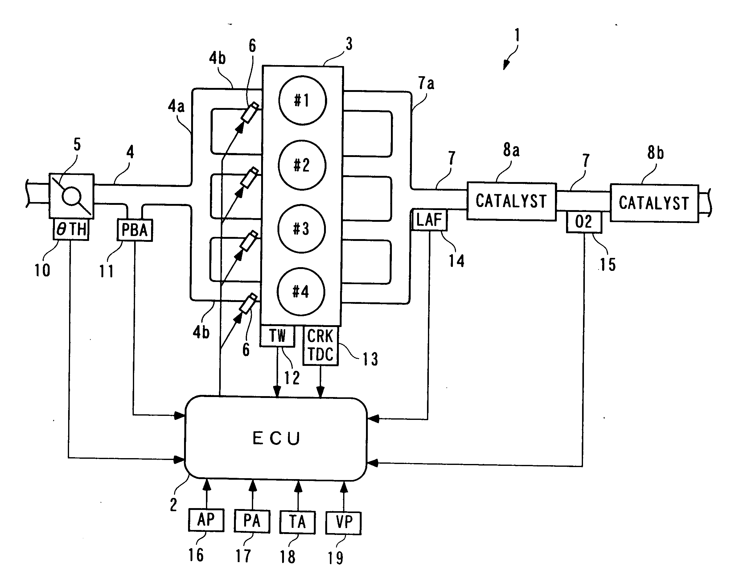
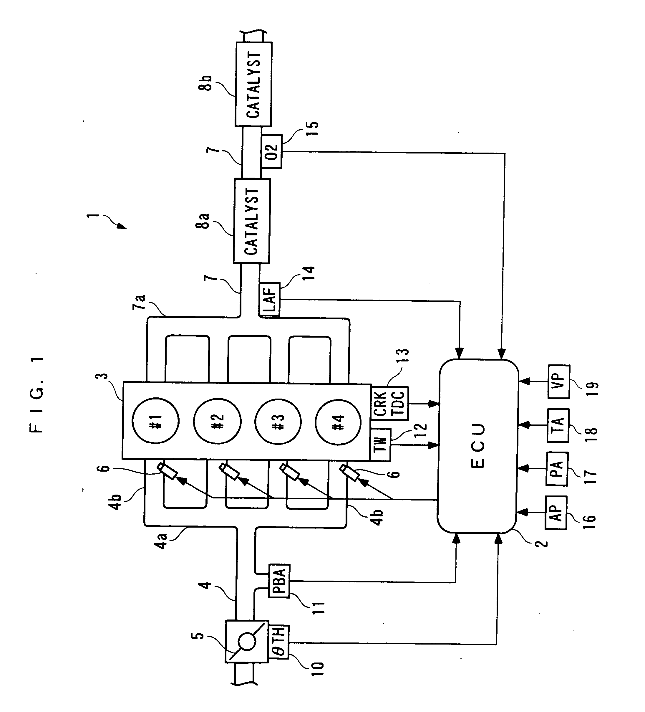
[0256] The invention will now be described in detail with reference to drawings showing preferred embodiments thereof. In these embodiments, a control device (control method, control unit, engine control unit) according to the invention is configured to control the air-fuel ratio of a mixture supplied to an internal combustion engine. Referring first to FIG. 1, there is schematically shown the arrangement of a control device 1 according to the invention and an internal combustion engine 3 to which the control device 1 is applied. As shown in the figure, the control device 1 includes an ECU 2 which controls the air-fuel ratio of an air-fuel mixture supplied to the internal combustion engine (hereinafter simply referred to as “the engine”) 3, as described hereinafter, according to operating conditions of the engine 3.

[0257] The engine 3 is an inline four-cylinder gasoline engine installed on an automotive vehicle, not shown, and has first to fourth cylinders #1 to #4. In the vicinity ...

tenth embodiment

[0492] Next, description will be given of a control device according to a Similarly to the FIG. 39 example, the present control device 1 is applied to an engine 3 provided with no LAF sensor 14, and having an O2 sensor 15 arranged at a location downstream of a second catalytic device 8b. Therefore, as shown in FIG. 44, in this control device 1, a sampled value of the output Vout from the O2 sensor 15 and a decimation value DKCMD′ of the target air-fuel ratio are used for calculation of the predicted value PREVO2 by a state predictor 22 and identification of the model parameters a1, a2, b1 by an onboard identifier 23.

[0493] Further, in a predictive algorithm used by the state predictor 22, a formula for calculating the predicted value PREVO2 is defined by an equation (76) shown below, based on the controlled object model expressed by the equation (60). On the other hand, an identification algorithm used by the onboard identifier 23 is expressed by equations (77) to (84) shown below....

ninth embodiment

[0494] According to the above control device 1, the same advantageous effects as provided by the control device 1 of the ninth embodiment can be obtained. In addition, since the control system 1 of the present embodiment requires no LAF sensor 14, it is possible to reduce manufacturing costs.

[0495] Further, in the control system 1 of the tenth embodiment, similarly to the control device 1 of the ninth embodiment, the decimation filters 40 may be replaced e.g. by samplers capable of sampling the target air-fuel ratio KCMD at the sampling period of ΔTsk, and the SDM controller 29 or the DM controller 30 may be used in place of the DSM controller 24.

[0496] Although in each of the above embodiments, the control device of the invention is used to control the air-fuel ratio in the internal combustion engine 3, this is not limitative, but the invention can be widely applied to control devices for controlling other controlled objects. Further, the ADSM controller 20 and the PRISM controlle...


PUM


Abstract

There are provided a control device, a control method, a control unit, and an engine control unit, which are capable of controlling a controlled object with relatively large phase delay and dead time, while attaining elimination of lag in control timing between the input and output of the controlled object and improvement of control accuracy at the same time. A state predictor calculates a deviation (output deviation) between an output from an oxygen concentration sensor and a predetermined target value at a predetermined deviation calculation period. Then, a DSM controller calculates a target air-fuel ratio for converging the output from the oxygen concentration sensor to the predetermined target value, according to the calculated deviation, based on any one of a Δ modulation algorithm, a ΔΣ modulation algorithm, and a ΣΔ modulation algorithm at a predetermined calculation period shorter than the predetermined deviation calculation period.

Description

REFERENCE TO RELATED APPLICATIONS [0001] This is a Division of application Ser. No. 10 / 366,670, filed Feb. 14, 2003. The disclosure of the prior application is hereby incorporated by reference herein in its entirety.BACKGROUND OF THE INVENTION [0002] 1. Field of the Invention [0003] This invention relates to a control device, a control method, a control unit, and an engine control unit, for calculating a control input to a controlled object e.g. based on a ΔΣ modulation algorithm so as to control an output from the controlled object. [0004] 2. Description of the Prior Art [0005] Conventionally, a control device of the above-mentioned kind has been disclosed e.g. in Japanese Laid-Open Patent Publication (Kokai) No. 2001-154704. The control device includes detection means that detects an output from a controlled object (i.e. controlled system) and then outputs a detection signal of an analog quantity indicative of the sensed output, deviation-calculating means that calculates a deviat...

Claims


Application Information

Patent Timeline
Patent Type & Authority Applications(United States)
IPC IPC(8): B60T7/12F02D41/14G05B11/36F02D45/00G05B13/02G05B13/04G05B21/02H03M3/02
CPCF02D41/1441F02D41/1456F02D41/1479F02D41/2454F02D41/2477F02D2041/1415G05B13/047F02D2200/0404F02D2200/0406F02D2200/0414F02D2200/703G05B13/042F02D2041/1433
Inventor YASUI, YUJI
Owner HONDA MOTOR CO LTD
Learn More