Further improved reversing flow catalytic converter for internal combustion engines

a technology of catalytic converter and reverse flow, which is applied in the direction of engines, machines/engines, mechanical equipment, etc., can solve the problems of affecting the performance of the engine, so as to achieve the effect of improving the compact valve structur

Inactive Publication Date: 2006-12-21
SMART MUFFLER CORP
View PDF4 Cites 10 Cited by
  • Summary
  • Abstract
  • Description
  • Claims
  • Application Information

AI Technical Summary

Benefits of technology

[0014] It is accordingly an object of the present invention to provide a further improved reversing flow catalytic converter system for treating exhaust gases from an internal combustion engine, which system includes an improved compact valve structure incorporated in the converter as well as an improved safeguard system to protect the catalyst and converter from overheating and including an improved method for monolith heat addition by diesel injection into the central core of the monolith.
[0015] Another object of the present invention is to provide a further improved reversing flow catalytic converter system for treating exhaust gases from an internal combustion engine which has a compact structure for efficient performance, minimal heat loss, and mechanical simplicity.

Problems solved by technology

A problem relating to catalytic converters for internal combustion engines, such as the prior art reversing flow catalytic converter for internal combustion engines disclosed in U.S. Pat. No. 6,148,613, is overheating Lean burn combustion systems for fuel-efficient vehicles are particularly hard on exhaust after-treatment systems because excessive oxygen is always present in the exhaust.
Under such circumstances, any engine management problems that result in excessive fuel in the exhaust, will generally damage exhaust after-treatment system due to overheating.
If a fuel management problem occurs, a large amount of the excess fuel delivered to the engine can pass through it and into the engine exhaust.
Further temperature rise will cause collapse of the substrate and eventual melt-down will occur when it is heated to 1400-1450° C. A detrimental uncontrolled temperature rise can damage a catalyst in less than 20 seconds.
The large amount of excessive fuel from the engine pulls down the catalyst temperature.
In this type of catalyst protection mode, however, the carbon monoxide content of the exhaust gas is undesirably very high.
However, for lean burn systems such as diesel or dual fuel engines, the excessive fuel will not cool down the catalyst temperature because of the presence of a high concentration of oxygen in the exhaust.
Furthermore, lean burn systems cannot burn stoichiometric fuel / air mixtures because of knocking restrictions.
Engine fuel will need to be added to the exhaust stream during idle and low power operation of the engine in order to maintain an oxidation temperature sufficient to convert CO and hydrocarbons (including particulates), however, a considerably lesser amount of fuel than would be required by a conventional uni-directional oxidation catalyst.
For this reason, addition of fuel can also result in overheating of the catalyst, if too much fuel is added.
Disadvantageously, prior art devices such as the type disclosed in U.S. Pat. No. 6,148,613 lack a safeguard system to protect such reversing flow catalytic converter from overheating, as may arise under any one or more of the conditions explained above.
The improved patent however, suffers from use of a rotating compact valve that is prone to having a high degree of friction drag due to its design and requirement for low leakage of exhaust gas across the valve.
The improved patent application also suffers from a neutralizing spring return design with two compressed springs such that the spring return is not force-balanced at the shaft and therefore prone to shaft wear.

Method used


Image

  • Further improved reversing flow catalytic converter for internal combustion engines
  • Further improved reversing flow catalytic converter for internal combustion engines
  • Further improved reversing flow catalytic converter for internal combustion engines

Examples


Embodiment Construction

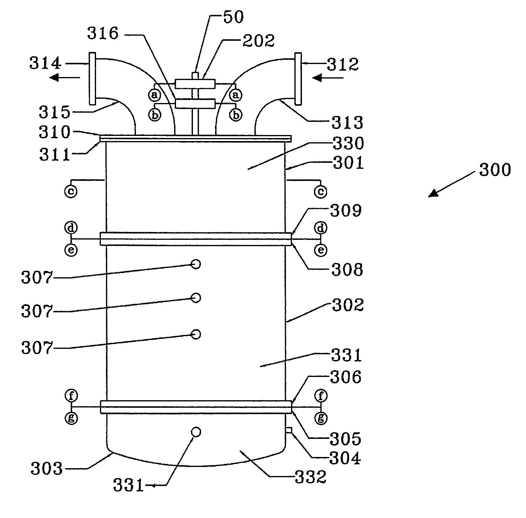
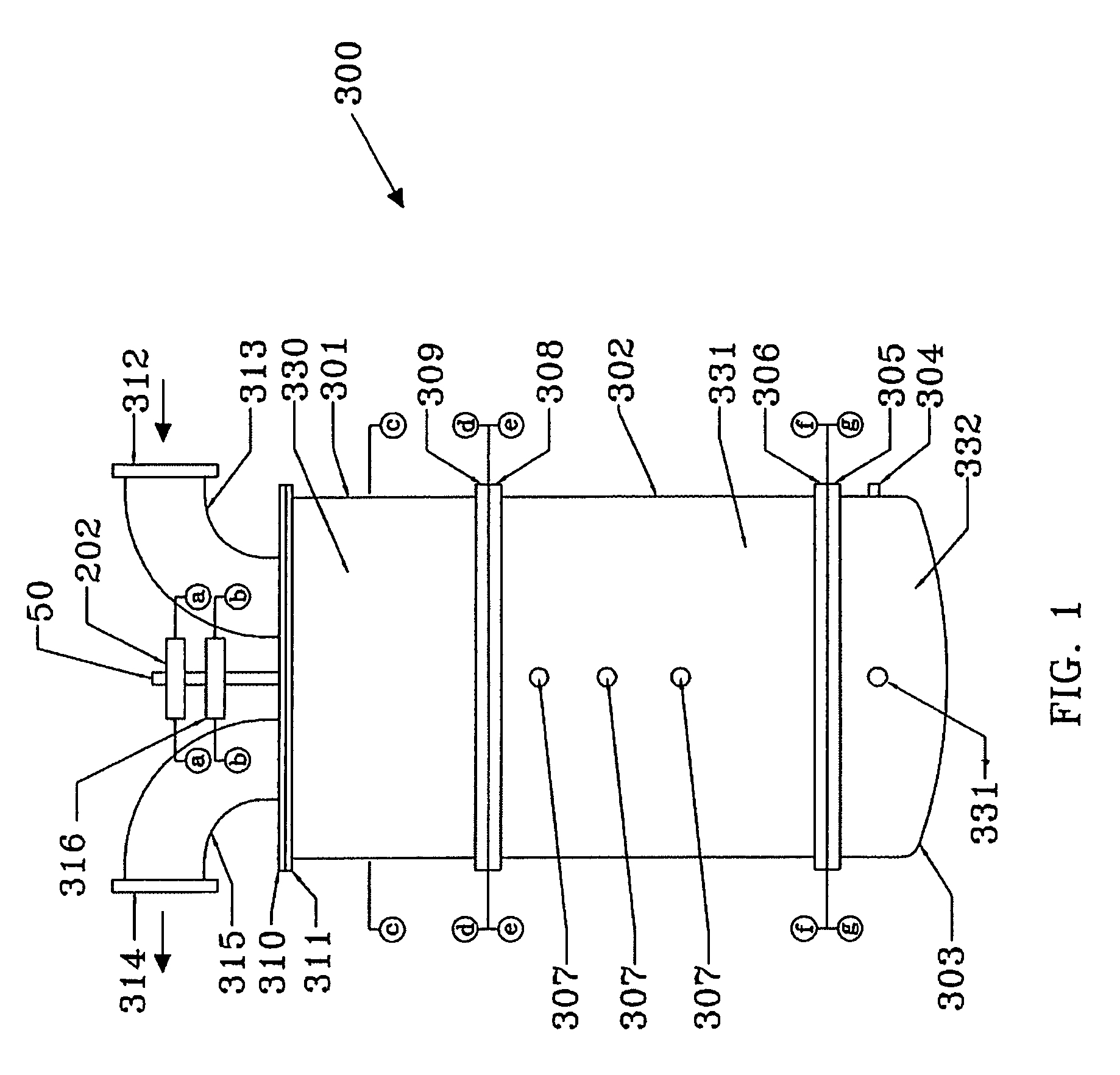
[0064]FIG. 1 illustrates a further improved catalytic converter 300 in accordance with an embodiment of the present invention which incorporates a safeguard system to inhibit overheating the catalyst monoliths, an improved valve assembly, an improved spring return and an improved monolith can and re-direction bowl with improved diesel fuel injection.

[0065] With reference to FIG. 1, the catalytic converter 300 comprises a improved container 302 and improved valve housing 301 with a similar function as described in U.S. patent application Ser. No. 11 / 212,608. A rotary actuator 202 and a center return mechanism 316 are mounted on the drive shaft 50 of the valve flapper parts 348 and 349. The rotary actuator 202 is controlled to periodically rotate the valve flapper parts 348 and 349 between the first and the second positions to reverse gas flow through the container 302.

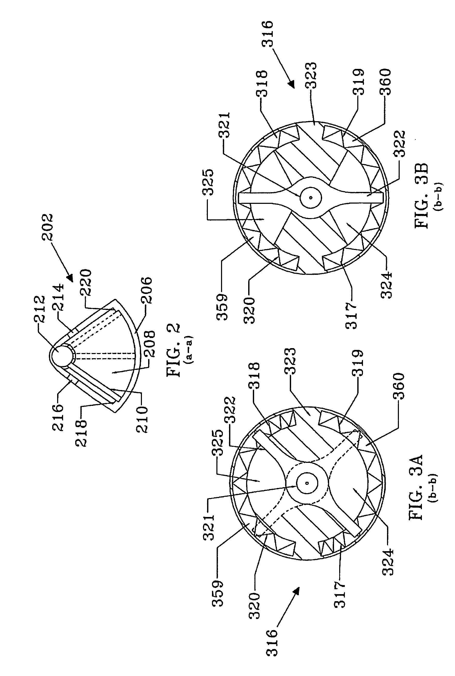
[0066] As shown in FIG. 2, the rotary actuator 202 includes a housing 206 which encloses a pressure chamber 208. A ...


PUM


Abstract

A further improved compact reversing flow catalytic converter with protection from overheating includes an improved valve unit which directs exhaust gases through a container filled with catalytic material to permit a bypass of catalytic material when a temperature of the material exceeds a predetermined threshold. The container defines a U-shaped gas passage that communicates with two chambers at the top of the container. The improved valve unit is mounted to the top of the container and includes two container chamber extension cavities, an improved intake cavity and an improved exhaust cavity. The improved valve unit includes an improved valve flapper and two conjoined valve walls each wall with two openings therethrough. The improved valve flapper rotates around normal central axis between a first, a second and third positions. When overheating of the catalytic material is predicted, a controller relinquishes control of the improved valve flapper and an improved center return mechanism rotates the improved valve flapper to a third position, in which each of the valve openings communicates with both inlet and exhaust ports so that the exhaust gas flow bypasses catalytic material. A fuel injection system under control of the controller is used so that measured amounts of fuel can be injected into the container reaction core to enhance oxidation. The catalytic material is thus protected from damage due to overheating. The advantage is a compact, reliable, highly efficient further improved catalytic converter that is inexpensive to manufacture, durable, and adapted for extended service life. The improved valve may driven by a stepper motor that moves and holds the valve to its three positions including bypass, forward and reverse flow. An alternate version also replaces the oxidizing flow-through monolith with an oxidizing filter trap.

Description

[0001] The present invention relates to catalytic converters for internal combustion engines, and in particular, to a further improved reversing flow catalytic converter over that disclosed in U.S. patent application Ser. No. 11 / 218,608 filed Aug. 29, 2005 in the name of some of the inventors herein for treating exhaust gases from internal combustion engines.BACKGROUND OF THE INVENTION [0002] A problem relating to catalytic converters for internal combustion engines, such as the prior art reversing flow catalytic converter for internal combustion engines disclosed in U.S. Pat. No. 6,148,613, is overheating Lean burn combustion systems for fuel-efficient vehicles are particularly hard on exhaust after-treatment systems because excessive oxygen is always present in the exhaust. For example, the exhaust of diesel dual fuel (DDF) engines, which is one type of diesel engine, normally contains more than 5% volumetric oxygen after combustion. Under partial load the surplus of oxygen in the...

Claims


Application Information

Patent Timeline
Patent Type & Authority Applications(United States)
IPC IPC(8): F01N3/10
CPCF01N1/084F01N13/0097F01N3/035F01N3/2053F01N3/2093F01N3/24F01N11/002F01N2390/00F01N2410/00F01N2410/02F01N2410/08F01N2470/22F01N2560/06Y02T10/47F01N3/031Y02T10/40
Inventor ZHENG, MINGMIROSH, EDWARD A.READER, GRAHAM T.DESCHNER, BERNIE
Owner SMART MUFFLER CORP
Why Eureka
Try Eureka