Fuel injection system and purging method

Active Publication Date: 2006-12-21
ANSALDO ENERGIA SWITZERLAND AG
View PDF7 Cites 21 Cited by
  • Summary
  • Abstract
  • Description
  • Claims
  • Application Information

AI Technical Summary

Benefits of technology

[0020] Whereas the above paragraphs mention only a single fuel supply component fitted with a sensor, the invention also embraces a plurality of fuel supply components that undergo a purge sequence, and a corresponding plurality of gas sensors for detecting the concentration of the gaseous fuel inside the fuel supply components. In such systems, each fuel supply compone

Problems solved by technology

Otherwise, there is a risk that in some circumstances the residual fuel might mix with air and undergo combustion close to, or within, the fuel supply component or components leading to overheating and damage of the same.
Moreover, even in the absence of air, if the residual fuel is subject to elevated temperatures then this can lead to fuel decomposition and the undesirable formation of soot with the potential to block the fuel supply component or components.
There is a risk that ignition of the fuel can take place close

Method used


Image

  • Fuel injection system and purging method
  • Fuel injection system and purging method
  • Fuel injection system and purging method

Examples


Embodiment Construction

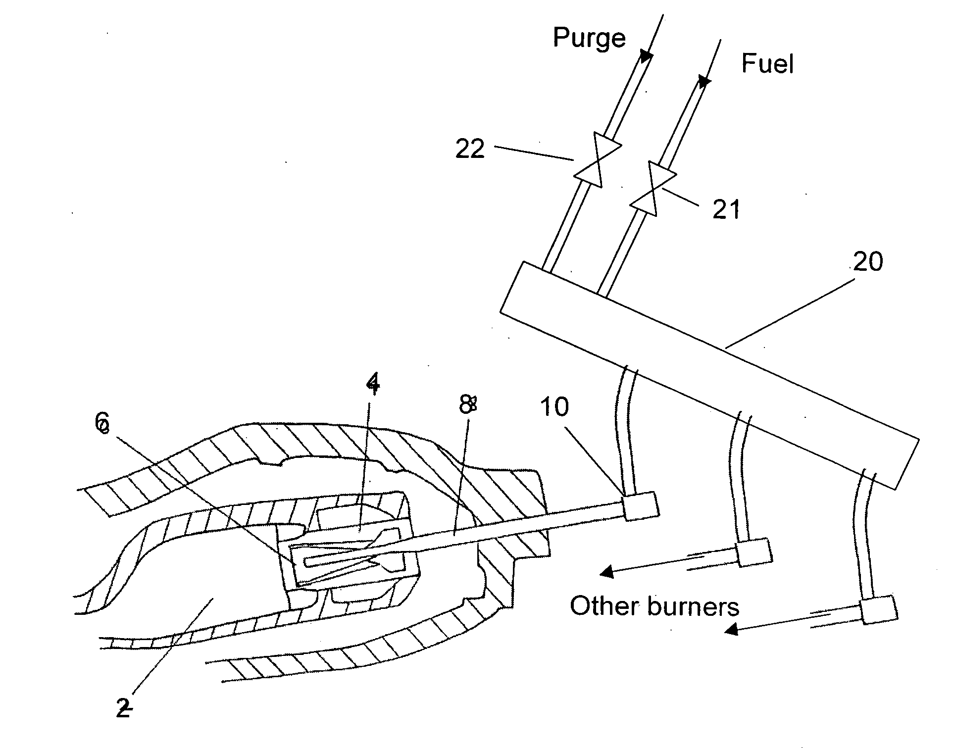
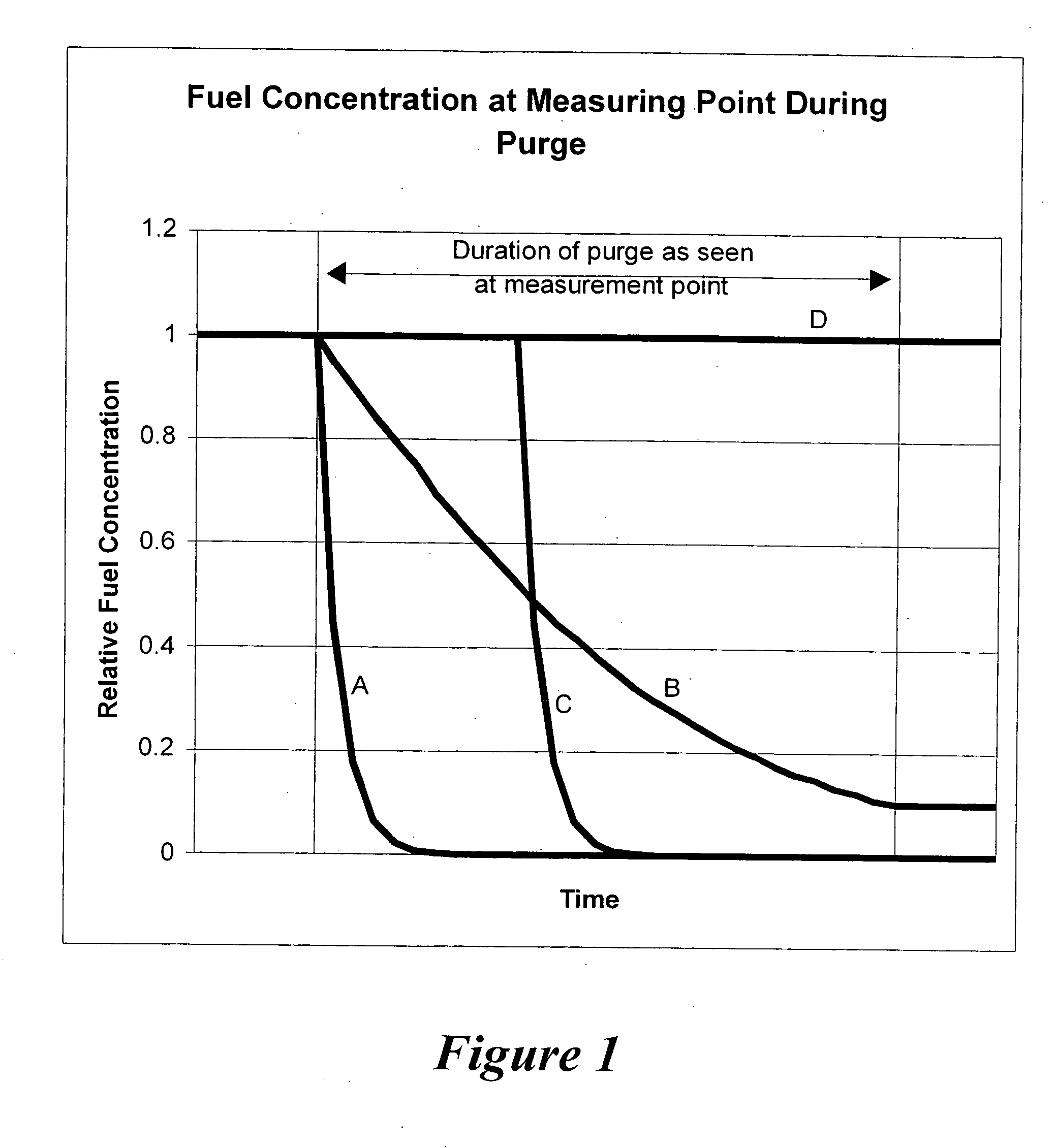
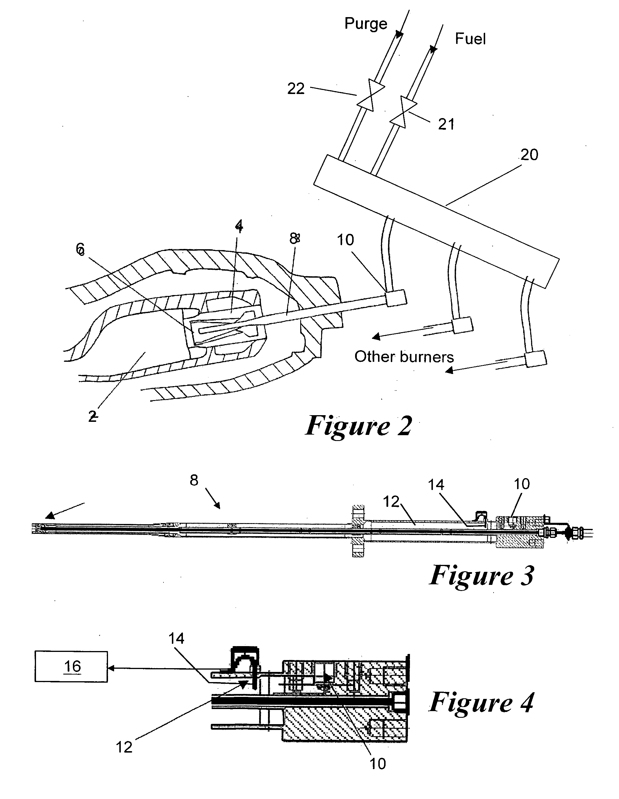
[0029]FIG. 1 shows a typical variation in fuel concentration at a point in a fuel lance during a nitrogen purge sequence. This purge sequence is initiated in the fuel injection system by simultaneously closing the fuel supply valve to the fuel manifold and opening the purge gas supply valve. The purge sequence is terminated by the closure of the purge gas supply valve. The four lines shown in FIG. 1 represent the relative fuel concentration versus time response for a fuel injection system as follows. [0030] Line A All valves operating correctly. [0031] Line B Insufficient purge gas flow due to problems such as one of the following: [0032] (i) check valve that is operating poorly (partially blocked or not opening fully; [0033] (ii) blocked or damaged fuel line; or [0034] (iii) incorrect operation of the overall purge gas flow. [0035] Line C A check valve that has a tendency to stick during operation. [0036] Line D A check valve that is stuck in the open position.

[0037] A similar rel...


PUM


Abstract

A fuel injection system has a fuel lance for supplying gaseous fuel to the burner of a gas turbine engine. The fuel lance includes a gas sensor that is used to monitor the concentration of the methane fuel inside the gas pilot channel of the fuel lance. The invention prevents overheating caused by the ignition of the methane fuel inside the fuel lance by monitoring the concentration of the methane fuel during the purge sequence and taking action if a critical fuel air mixture is reached.

Description

FIELD OF THE INVENTION [0001] The present invention relates to a fuel injection system, and in particular to a fuel injection system for supplying gaseous fuel such as methane to a burner or burners that fire into a combustion chamber such as a gas turbine engine or furnace. The present invention also relates to a method of purging the fuel injection system to remove any residual fuel that may be trapped in the fuel injection system. BACKGROUND OF THE INVENTION [0002] In a fuel injection system having multiple fuel supply components (such as the fuel lances described below), it is sometimes necessary to shut down one or more of the fuel supply components while at least one of the remaining fuel supply components continues to operate. In this case, there is a need to consider purging the fuel supply component or components that have been shut down to remove any residual fuel that may be trapped in the component or components. Otherwise, there is a risk that in some circumstances the ...

Claims


Application Information

Patent Timeline
IPC IPC(8): F02C3/22F23K5/06F23K5/18
CPCF23D2206/10F23D2209/30F23K2301/203F23K5/18F23K5/06F23K2300/203
Inventor NILSSON, ULF ERIK
Owner ANSALDO ENERGIA SWITZERLAND AG
Why Eureka
Try Eureka