
Electrochemical apparatus with barrier layer protected substrate

a technology of electrochemical apparatus and substrate, which is applied in the direction of cell components, flat cell grouping, sustainable manufacturing/processing, etc., can solve the problems of insufficient electrochemical properties, insufficient capacity density, energy density, and power density of thin-film batteries, per volume and weight, and achieve good electrochemical properties, prevent diffusion, and improve performance and reliability

Active Publication Date: 2006-12-21
SAPURAST RES
View PDF99 Cites 152 Cited by
  • Summary
  • Abstract
  • Description
  • Claims
  • Application Information

AI Technical Summary

Benefits of technology

[0011] When vacuum deposited into thin-films, these materials may preferably include post-deposition annealing at high temperatures in order to improve their crystallinity, which is directly related to development of their full range of electrochemical properties. For an electrochemical apparatus, which employs such a thin-film battery, to become thinner, mainly the inert, electrochemically inactive part of the electrochemical apparatus should become thinner. One approach may be to build the battery on thin, metal foil substrates instead of thick, bulky ceramic ones. Metal foils are more flexible, thinner, and less expensive than ceramic substrates of the same footprint. Furthermore, they are easily available in much larger areas which translates into substantial cost savings in manufacturing.
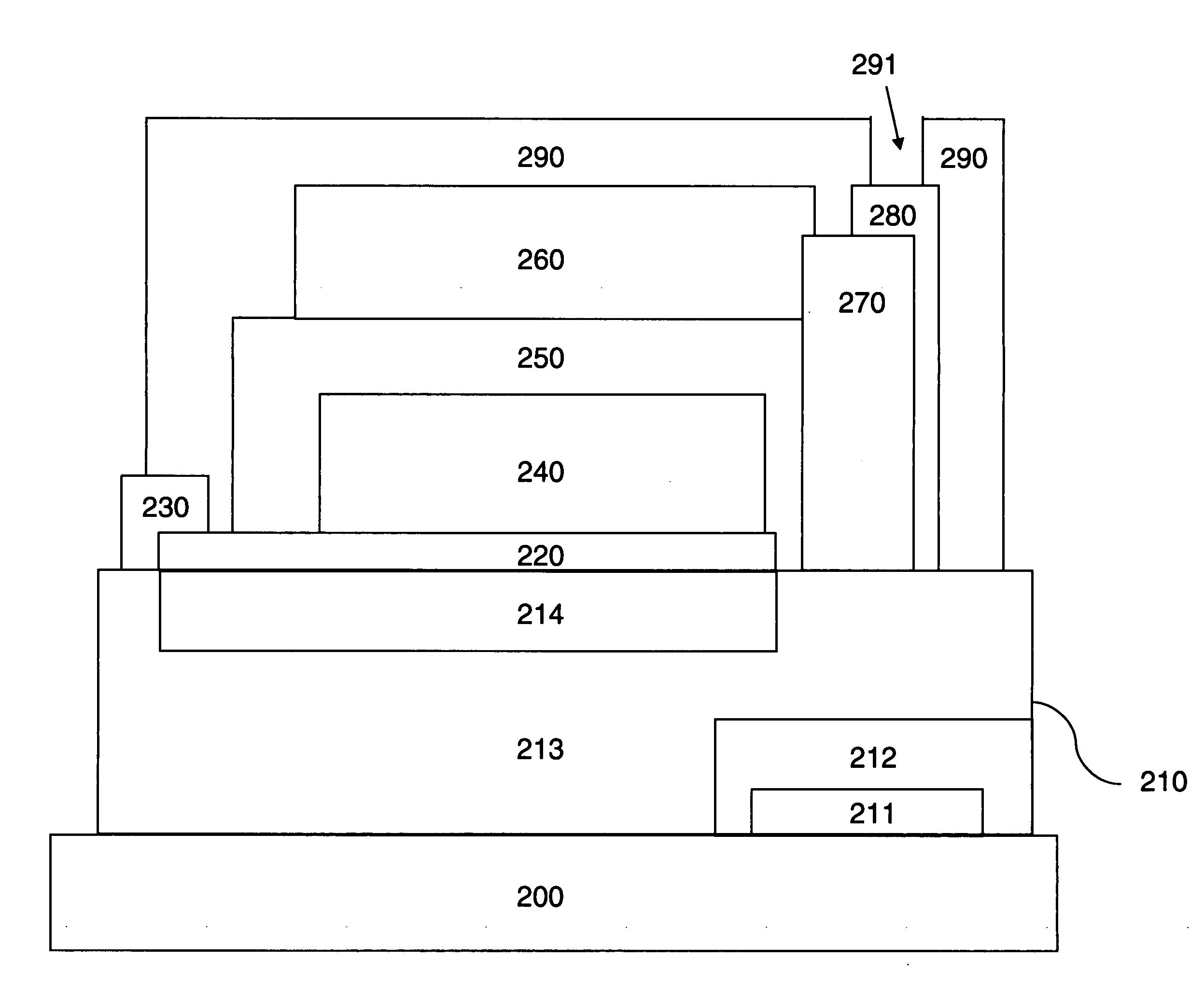
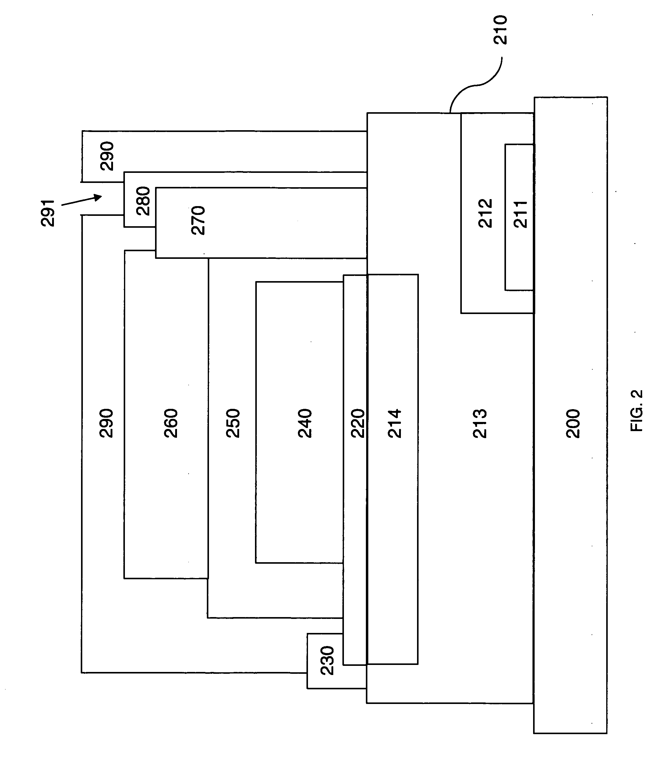
[0035] Barrier sublayer materials for a diffusion barrier layer of the present invention may include, but are not limited to, thin-films of amorphous Si3N4, SiC, ZrN, and TiC, among others. These are exemplary of compounds which may effectively serve as barriers due to their ion blocking properties, amorphous structure, and chemical inertness to the substrate, as well as to the battery part of the electrochemical apparatus. The pre-eminent characteristics of these barrier layer chemistries are their inherent ability to retain their amorphous, as-deposited state and their diffusion blocking properties up to substantially high temperatures, for example 700° C., and for longer periods at those temperatures, for example 2 hours, during the preferred LiCoO2 crystallization post-deposition anneal process. As a result, thin-film batteries fabricated on metal foils with such barrier layers retain good electrochemical properties for equivalently configured thin-film batteries that are fabricated onto ceramic substrates, but with the added benefits of being flexible, much thinner, and cheaper.

Problems solved by technology

The positive cathode material may be insufficiently crystalline in the as-deposited state and, associated with this fact, may exhibit insufficient electrochemical properties (see, for example, Wang et al., supra).
The anneal process, which is applied immediately after the deposition of the positive cathode, may limit the choice of materials for the substrate and positive cathode current collector, thereby limiting, in turn, the capacity density, energy density, and power density of the thin-film battery, both per volume and weight.
According to U.S. Pat. No. 6,280,875, native titanium oxide on a Ti substrate is not inert enough to prevent adverse reactions from occurring between a Ti substrate and the battery components.
This approach is severely restricted because the choice of substrate materials is limited to materials capable of forming a native surface oxide during the anneal step of the positive cathode.
Fabricating solid-state, thin-film secondary batteries by depositing, for example, high-temperature cathode materials directly onto metallic substrates, including flexible foils, other than Zr, and then annealing at high temperature, such as 700° C. in air for 1 hour, may result in the positive cathode and substrate materials reacting detrimentally to such an extent that the positive cathode is rendered useless.
Pure Ti and Zr substrates are also relatively expensive.
Prior thin-film batteries do not disclose the use of an effective barrier layer between the substrate and the battery, and, therefore, provide potential negative observations.

Method used


Image

  • Electrochemical apparatus with barrier layer protected substrate
  • Electrochemical apparatus with barrier layer protected substrate
  • Electrochemical apparatus with barrier layer protected substrate

Examples


Embodiment Construction

[0056] It should be understood that this invention is not limited to the particular methodology, protocols, etc., described herein and, as such, may vary. The terminology used herein is for the purpose of describing particular embodiments only, and is not intended to limit the scope of the present invention, which is defined solely by the claims.

[0057] As used herein and in the claims, the singular forms “a,”“an,” and “the” include the plural reference unless the context clearly indicates otherwise.

[0058] All patents and other publications identified are incorporated herein by reference in their entirety for the purpose of describing and disclosing, for example, the methodologies, apparatuses, and compositions described in such publications that might be used in connection with the present invention. These publications are provided solely for their disclosure prior to the filing date of the present application. Nothing in this regard should be construed as an admission that the in...


PUM

PropertyMeasurementUnit
Temperatureaaaaaaaaaa
Fractionaaaaaaaaaa

Abstract

The present invention relates to apparatus, compositions and methods of fabricating high performance thin-film batteries on metallic substrates, polymeric substrates, or doped or undoped silicon substrates by fabricating an appropriate barrier layer composed, for example, of barrier sublayers between the substrate and the battery part of the present invention thereby separating these two parts chemically during the entire battery fabrication process as well as during any operation and storage of the electrochemical apparatus during its entire lifetime. In a preferred embodiment of the present invention thin-film batteries fabricated onto a thin, flexible stainless steel foil substrate using an appropriate barrier layer that is composed of barrier sublayers have uncompromised electrochemical performance compared to thin-film batteries fabricated onto ceramic substrates when using a 700° C. post-deposition anneal process for a LiCoO2 positive cathode.

Description

RELATED APPLICATIONS [0001] The present application claims the benefit under 35 U.S.C. § 119(e) of U.S. provisional application Ser. No. 60 / 690,697, filed on Jun. 15, 2005, entitled “Electrochemical Apparatus with Barrier Layer Protected Substrate,” which is incorporated herein by reference.FIELD OF THE INVENTION [0002] The field of this invention is the apparatus, composition, and fabrication of lithium-based, solid-state, thin-film, secondary and primary batteries with improved capacity density, energy density, and power density, and preferably with flexible form factor and crystalline LiCoO2, LiNiO2, LiMn2O4 cathodes and derivative materials. BACKGROUND OF THE INVENTION [0003] The following passage describes the need and evolution of the subject technology in the field of thin film batteries. [0004] Thin-film batteries may be fabricated by sequential vacuum depositions of layered battery components onto a given substrate in, for example, the following order: positive cathode curr...

Claims


Application Information

Patent Timeline
IPC IPC(8): H01M2/02B05D5/12H01M4/139H01M4/52H01M4/525H01M10/052H01M10/0585H01M10/36H01M50/126H01M50/133H01M50/141
CPCH01M2/0275Y10T29/49115H01M2/0285H01M2/0287H01M2/10H01M2/1094H01M4/02H01M4/0421H01M4/139H01M4/525H01M6/40H01M10/0436H01M10/052H01M10/0585H01M2004/021Y02E60/122H01M2/0277Y02E60/10H01M50/124H01M50/24Y02P70/50H01M50/126H01M50/141H01M50/133
Inventor SNYDER, SHAWN W.NEUDECKER, BERND J.
Owner SAPURAST RES
Learn More