
Fiber-optic biosensor and biosensing methods

a biosensor and fiber optic technology, applied in the field of biosensors, can solve the problems of inability to detect the body, the predisposition to fatal venous thrombosis, and the inability to accurately detect the body, so as to improve the sensing effect, shorten the assay time, and enhance the fluorescence

Inactive Publication Date: 2006-12-21
CINCINNATI UNIV OF +1
View PDF28 Cites 15 Cited by
  • Summary
  • Abstract
  • Description
  • Claims
  • Application Information

AI Technical Summary

Benefits of technology

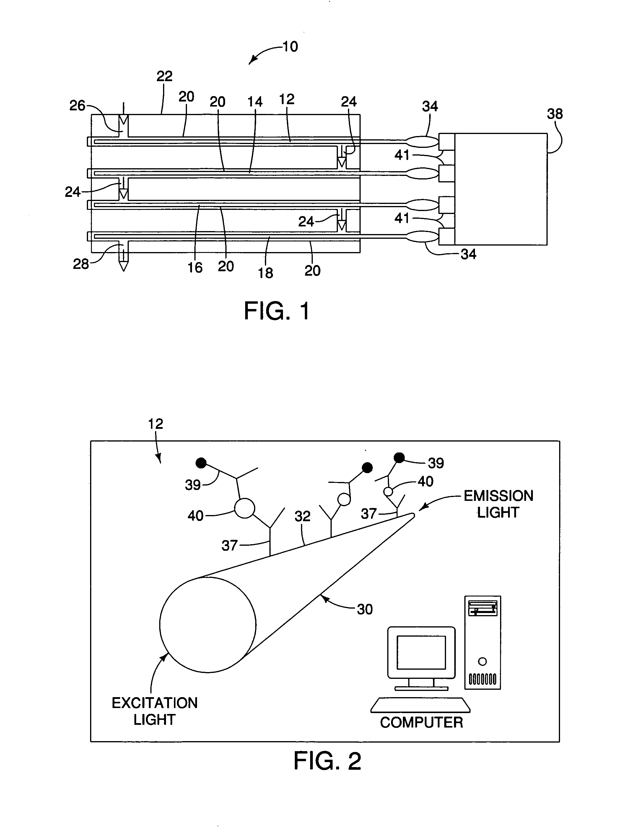
[0011] Embodiments of the invention additionally and advantageously include using convective flow to expose a sample and any associated reagents to the optical waveguides, which optimizes sensing and shortens assay times.
[0012] Additionally, fluorescence enhancers may be provided with embodiments of the invention to enhance fluorescence where the target sensing ranges of a particular biomarker are otherwise relatively low. Fluorescence enhancement includes placing a nanometal particle at a particular distance from a fluorophore to enhance fluorescence emission of the fluorophore.

Problems solved by technology

When the haemostatic system in human body is unregulated, due to either coagulation problem, or more commonly, due to impaired capacity of natural anticoagulant mechanism caused by anticoagulant deficiencies, the body has a predisposition to fatal venous thrombo-embolism.
Although very accurate, it is time-consuming (hours to days), expensive, and technically complicated.
However, they usually provide only qualitative single biomarker information and most of the assay kits are relatively expensive, and may only be used a single time.

Method used


Image

  • Fiber-optic biosensor and biosensing methods
  • Fiber-optic biosensor and biosensing methods
  • Fiber-optic biosensor and biosensing methods

Examples


Embodiment Construction

[0041] To obtain accurate, rapid, and cost-effective disease diagnosis and prognosis, the invention provides for simultaneously detecting and quantifying one or more biomarkers, thereby permitting physicians, researchers and other personnel to accurately but quickly identify cardiovascular diseases and / or cardiac events. An optical waveguide, fluorophore mediated, multi-analyte immuno-biosensing method and biosensing device are provided by embodiments of the invention, and afford medical and other personnel with an invaluable diagnostic and prognostic tool.

[0042] While it is contemplated that embodiments of the invention may be used to detect and quantify a multitude of cardiovascular biomarkers and analytes, for purposes of illustration, embodiments of the invention will be shown and described in connection with other disease-representing biomarkers, as well as food, environmental and safety / security related markers. More particularly, while the invention should not be construed a...


PUM


Abstract

A method for biosensing that includes passing, via convective flow, a sample believed to contain one or more target biomarkers through a microfluidic channel and over the surface of an optical waveguide that has been prepared to bind the one or more target biomarkers, and sensing for an emission output from the optical waveguide at a wavelength that is characteristic of the binding of the target biomarker. A biosensor device that includes a module defining at least one microfluidic channel, an optical waveguide exposed along at least a portion of its length to fluid flow within the microfluidic channel, where a surface of the optical waveguide being prepared to bind a target biomarker, and an excitation source to couple an excitation wavelength of light into the optical waveguide. The device also includes a sensor for detecting emission light from the optical waveguide at an emission wavelength characteristic of binding of the target biomarker.

Description

REFERENCE TO RELATED APPLICATION AND PRIORITY CLAIM [0001] This application is a continuation-in-part of application Ser. No. 11 / 190,199, filed Jul. 26, 2005, and entitled “Enhancement of Sensitivity of Fluorophore Mediated Biosensing and Bioimaging,” which in turn claims the benefit under 35 U.S.C. §119 of earlier filed provisional application Ser. No. 60 / 590,992, filed Jul. 26, 2005. Priority is claimed from that application under 35 U.S.C. §120. [0002] This application also claims the benefit under 35 U.S.C. §119 from co-pending provisional application serial number Ser. No. 60 / 653,543, filed Feb. 16, 2005.FIELD OF THE INVENTION [0003] The field of the invention is biosensors. A particular application of the invention is simultaneously detecting and quantifying one or more target biomarkers associated with a particular disease for rapid disease diagnosis and prognosis. BACKGROUND OF THE INVENTION [0004] Detection of target biomarkers permits the diagnosis and prognosis of a parti...

Claims


Application Information

Patent Timeline
IPC IPC(8): G01N33/543C12M1/34
CPCG01N21/6486G01N33/54373
Inventor KANG, KYUNG AIHAHN, CHONG H.
Owner CINCINNATI UNIV OF
Learn More