Method and apparatus for therapeutic EMR treatment on the skin

a technology of emr treatment and skin, applied in the field of optical radiation apparatus, can solve the problems of increasing the potential for epidermal damage, the use of more expensive pulsed light sources for various dermatological treatments, and the potential for damage thereto, and achieve good heat transfer properties

Inactive Publication Date: 2006-12-21
PALOMAR MEDICAL TECH +1
View PDF99 Cites 40 Cited by
  • Summary
  • Abstract
  • Description
  • Claims
  • Application Information

AI Technical Summary

Benefits of technology

[0016] In accordance with still another embodiment of the invention, the head includes an optically transparent channel for delivering optical radiation of a wavelength appropriate for effecting the treatment in the area, a head portion of a thermally conductive material mounted relative to the channel so that it moves over each segment to be treated of such area before the channel, and a thermal component which controls the temperature of the head portion, and thus of each skin segment prior to treatment. In particular, the component may cool the portion, and thus each skin segment prior to treatment and / or the component may heat the portion, and thus heat each segment prior to treatment. The head may include a block formed of a material having good heat transfer properties, the block being adapted to move over the area during treatment, the channel being formed through the block and the portion being a portion of the block which is forward of the channel as the block is moved over the area. The head portion forward of the channel may be divided into a first thermally conductive portion which is heated and a second thermally conductive portion which is cooled, which portions are thermally insulated from each other, the first portion heating the patient's skin to the depth where treatment is to be performed and the second portion then cooling the patient's epidermis prior to irradiation. The head may also include a portion of a thermally conductive material mounted relative to the channel so that it moves over each segment to be treated of the area after the channel; and a thermal component which cools such rear head portion, and thus each skin segment after treatment.
[0017] While for preferred embodiments, preheating of the skin in the treatment area is accomplished in conjunction with the use of CW radiation and movement of the head over the treatment area, this is not a limitation on the invention, and preheating of the treatment area is also advantageous when employed with a pulsed radiation source. For such applications, preheating could be achieved by heating the waveguide or the portion of the head in contact with the segment under treatment prior to treatment to heat the skin down to at least to the depth where treatment is desired to a temperature which temperature is below that at which thermal damage occurs; and to then cool the surface in contact with the epidermis to cool the epidermis before irradiation begins. This results in the area under treatment having an elevated temperature when irradiation begins, thereby reducing the energy required from the radiation source. Alternatively, a low energy radiation source, which can be either the same or different than that used for treatment, can be used to perform the preheating operation.

Problems solved by technology

However, in order to avoid injury to the patient, the duration of energy application to a given area of the patient's skin must be controlled, this generally resulting in the more expensive pulsed light sources being used for the various dermatological treatments.
Further, since the only way to get radiation to areas where treatment is desired, which areas are normally in the dermis, is to transmit the radiation to such area through the overlying epidermis, some portion of incident radiation is absorbed in the epidermis creating the potential for damage thereto.
This is a particular problem where melanin is being targeted in the dermis, as is for example the case for various hair removal treatments, since there is a substantial concentration of melanin in the lower portion of the epidermis at the dermal / epidermal (DE) junction.
This further increases the potential for epidermal damage.
Another problem in performing laser dermatology treatments, particularly when such treatment is to be performed over an area larger than the optical aperture of the applicator being utilized, is to obtain substantially uniform irradiation over the area so that sufficient radiation is applied to all portions of the area to achieve the desired treatment, while no portion of the area has so much radiation applied thereto as to cause thermal damage to the skin.
Such uniform irradiation is very difficult with a pulsed source which typically utilize a circular aperture.
If the spots do not overlap, there will be portions of the area under treatment which do not receive radiation and, unfortunately, the radiation output is frequently not uniform over the entire optical aperture, being greater near the center, and less at the edges.
However, this results in some portions of the area under treatment receiving at least a double dose of radiation, which poses a potential danger of thermal damage in these overlap areas.
Substantially uniform irradiation of a treatment area is therefore virtually impossible with a pulsed radiation source utilizing existing techniques.
Another problem which increases the energy required from the radiation source utilized is that, for existing systems, heating of the target to achieve the desired therapeutic effect is accomplished solely by radiation from the radiation source.
However, such preheating must be achieved in a way such that the cost of such preheating is not greater than the savings achieved by reduced requirements on the radiation source.
If contact cooling starts when the head is over the target area, this means that there is some delay, perhaps half a second to a second, between the time the head is applied to the patient's skin and the time the radiation source is fired.

Method used


Image

  • Method and apparatus for therapeutic EMR treatment on the skin
  • Method and apparatus for therapeutic EMR treatment on the skin
  • Method and apparatus for therapeutic EMR treatment on the skin

Examples


Embodiment Construction

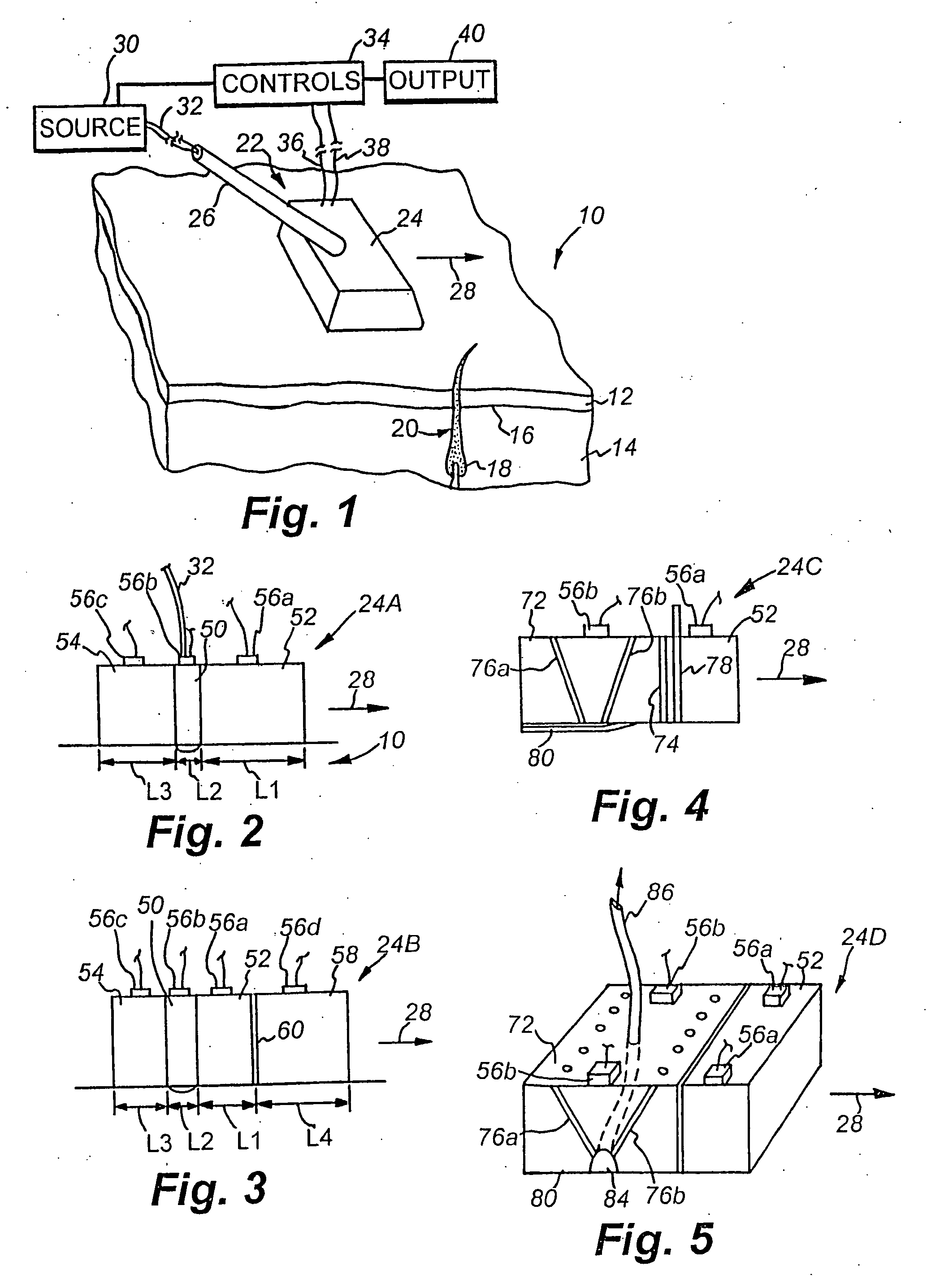
[0035]FIG. 1 illustrates a general system suitable for practicing the teachings of this invention. In FIG. 1, an area 10 of a patient's skin is shown on which a selected dermatologic treatment is to be performed. As indicated earlier, the treatment may be for removal of unwanted hair, tattoos, port wine stains, spider veins or other vascular lesions, etc. The patient's skin has an epidermal layer 12 and a dermal layer 14, with a dermal-epidermal (D / E) junction or basal layer 16 therebetween. While some dermatologic treatments may involve heating the epidermis 17, such as for example skin resurfacing, most dermatologic treatments which involve the use of optical radiation treat a condition located at a selected volume (sometimes hereinafter referred to as the target volume or target) within dermal layer 14. For example, when the dermatological treatment is hair removal, it may be desired to heat and destroy the bulb 18 of a hair follicle 20. While epidermis 12 might for example be 0....


PUM


Abstract

Methods and apparatus for dermatology treatment are provided which involve the use of continuous wave (CW) radiation, preheating of the treatment volume, precooling, cooling during treatment and post-treatment cooling of the epidermis above the treatment volume, various beam focusing techniques to reduce scattering and / or other techniques for reducing the cost and / or increasing the efficacy of optical radiation for use in hair removal and other dermatological treatments. A number of embodiments are included for achieving the various objectives indicated above.

Description

RELATED APPLICATIONS [0001] This application is a continuation of U.S. application Ser. No. 10 / 274,582, filed Oct. 21, 2000, which is a continuation of U.S. application Ser. No. 09 / 634,981, filed Aug. 9, 2000, entitled Heads for Dermatology Treatment now U.S. Pat. No. 6,511,475, which claims priority to U.S. application Ser. No. 09 / 078,055, filed May 13, 1998, entitled Method and Apparatus for Dermatology Treatment now U.S. Pat. No. 6,273,884 which application claims priority from provisional application Nos. 60 / 046,542 filed May 15, 1997 and 60 / 077,726 filed Mar. 12, 1998, the subject matter of which are incorporated herein by reference.FIELD OF THE INVENTION [0002] This invention relates to apparatus for using optical radiation to treat dermatological problems and, more particularly, to heads for such apparatus which heads provide an elongated focus area at a selected depth and / or selected preconditioning, for example heating and / or cooling, of a treatment area. BACKGROUND OF THE ...

Claims


Application Information

Patent Timeline
Patent Type & Authority Applications(United States)
IPC IPC(8): A61B18/18A61B18/00A61B18/20A61N5/06A61B19/00A61F2/00A61F7/00A61N5/04
CPCA61B18/203A61B2018/00005A61B2018/00041A61N5/0617A61B2018/00476A61B2019/465A61B2018/00458A61B2090/065
Inventor ALTSHULER, GREGORY B.ANDERSON, R. ROX
Owner PALOMAR MEDICAL TECH
Why Eureka
Try Eureka