Laser light source device, exposure device, and mask inspection device using this laser light source device

a laser light source and exposure device technology, applied in the field of laser light source devices, exposure devices, and mask inspection devices using this laser light source device, can solve the problems of high conversion efficiency not being implemented, difficult to implement the necessary processing and adjustment accuracy, and difficult to condense all light. , to achieve the effect of high degree of integration

Inactive Publication Date: 2006-12-28
NIKON CORP
View PDF7 Cites 35 Cited by
  • Summary
  • Abstract
  • Description
  • Claims
  • Application Information

AI Technical Summary

Benefits of technology

[0019] By constructing the laser light source device according to the present invention as above, the wavelengths of the laser lights emitted from the laser light source are efficiently converted, so high power lights with short wavelength can be acquired. Also by constructing an exposure device and a mask inspection device using the wavelength conversion optical system according to the present invention, a semiconductor device with a high degree of integration can be implemented.

Problems solved by technology

However with the above method in which fibers are spatially bundled, it is difficult to condense all light to one point on the wavelength conversion crystal for wavelength conversion, and to satisfy the acceptance angle of this wavelength conversion crystal, therefore high conversion efficiency cannot be implemented.
It is possible to construct to form an image on the wavelength conversion optical system for each of the bundled fibers using a micro-lens array, but it is difficult to implement the necessary processing and adjustment accuracy to acquire high conversion efficiency.

Method used


Image

  • Laser light source device, exposure device, and mask inspection device using this laser light source device
  • Laser light source device, exposure device, and mask inspection device using this laser light source device
  • Laser light source device, exposure device, and mask inspection device using this laser light source device

Examples


example 1

[0056]FIG. 7 shows the first example of the laser light source device which emits an eighth-harmonic wave. This laser light source device 21 is comprised of a first laser light source section 22, second laser light source section 23, third laser light source section 28, first fiber amplifier section 24, second fiber amplifier section 25, third fiber amplifier section 29, first optical multiplexer 26, second optical multiplexer 27, and first to sixth wavelength conversion crystals 31 to 36.

[0057] The first laser light source section 22 is comprised of m number of laser light sources, and when the frequency of the laser light emitted from the first laser light source is ω0, the frequency of the laser light emitted from the m-th laser light source is set to be a frequency which is different from frequency ω0 by ω0+(m−1)·Δω. The first fiber amplifier section 24 is comprised of m number of fiber amplifiers which amplify each laser light emitted from the m number of laser light sources r...

example 2

[0070] Now the second example of the laser light source device which emits an eighth-harmonic wave of the fundamental frequency will be described using FIG. 8. This laser light source device 41 is comprised of a first laser light source section 42, second laser light source section 43, first fiber amplifier section 44, second fiber amplifier section 45, first optical multiplexer 46, second optical multiplexer 47 and first to sixth wavelength conversion crystals 51 to 56.

[0071] The first laser light source section 42 is comprised of m number of laser light sources, and when the frequency of the laser light emitted from the first laser light source is ω0, the frequency of the laser light emitted from the m-th laser light source is set to be a frequency which is different from the frequency ω0 by ω0+(m−1)·Δω. The first fiber amplifier section 44 is comprised of m number of fiber amplifiers, which amplify each laser light emitted from the m number of laser light sources respectively. T...

example 3

[0082] Now the third example of the laser light source device which emits an eighth-harmonic wave of the fundamental frequency will be described using FIG. 9. This laser light source deice 61 is comprised of a first laser light source section 62, second laser light source section 63, first fiber amplifier section 64, second fiber amplifier section 65, first optical multiplexer 66, second optical multiplexer 67 and first to sixth wavelength conversion crystals 71 to 76.

[0083] The first laser light source section 62 is comprised of m number of laser light sources, and when the frequency of the laser light emitted from the first laser light source is ω0, the frequency of the laser light emitted from the m-th laser light source is set to be a frequency which is different from the frequency ω0 by ω0+(m−1)·Δω. The first fiber amplifier section 64 is comprised of m number of fiber amplifiers, which amplify each laser light emitted from the m number of laser light sources respectively. The...


PUM

PropertyMeasurementUnit
wavelengthsaaaaaaaaaa
wavelengthaaaaaaaaaa

Abstract

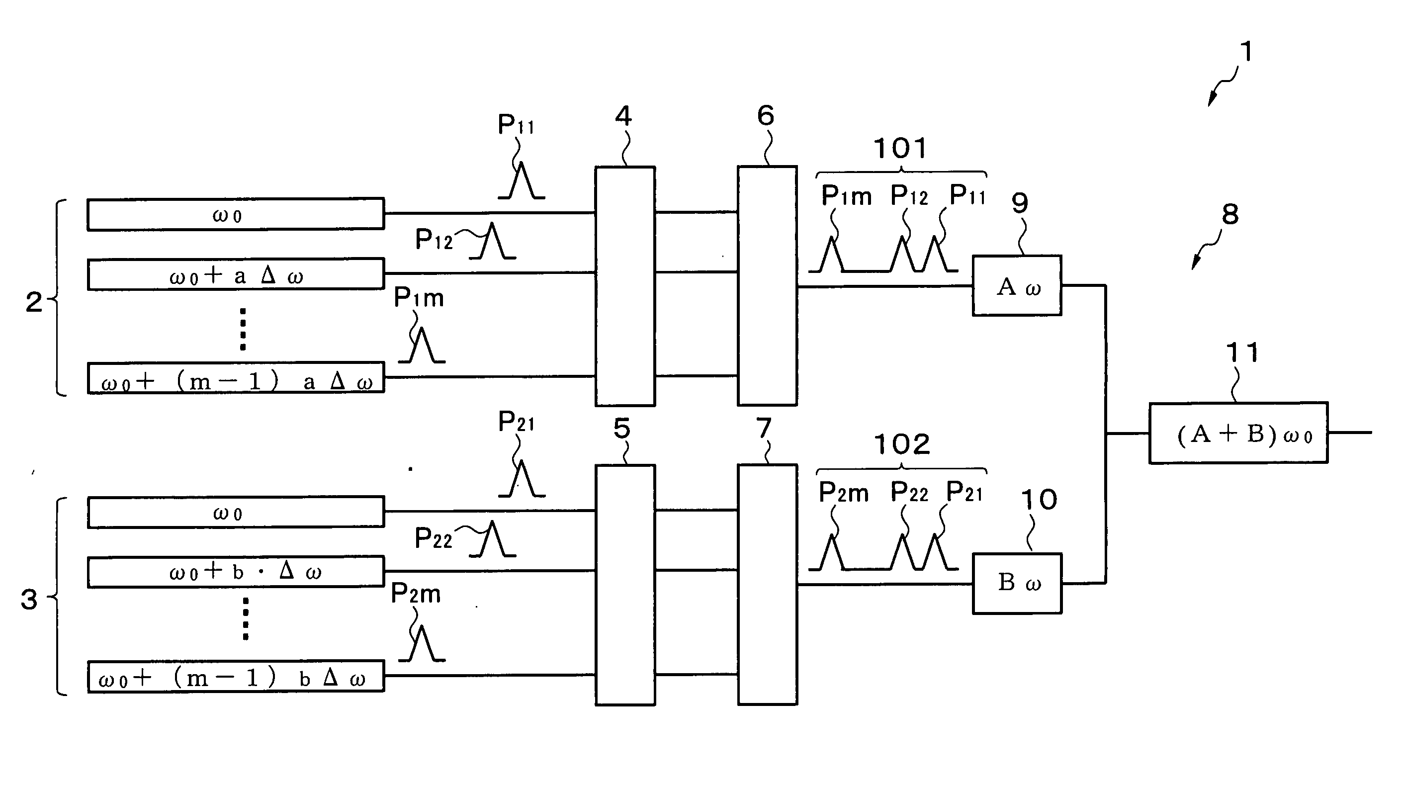
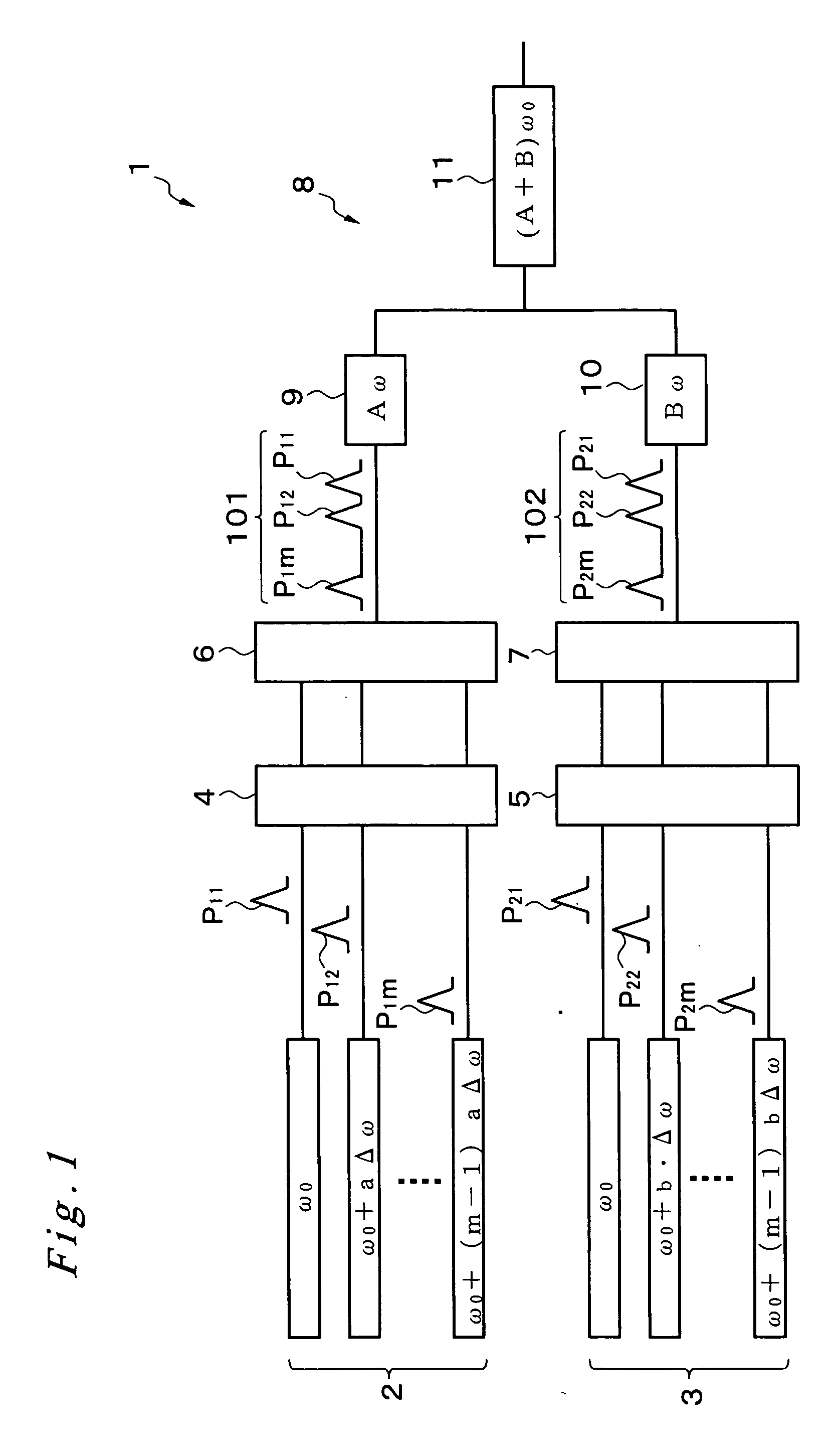
A laser light source device 1, comprising M number of laser light sources, of which frequency is shifted from a fundamental frequency by (m−1)·a·Δω, a first laser light source section 2 and a first fiber amplifier section 4 for amplifying these laser lights, a first optical multiplexer 6 for approximately coaxially superimposing the laser lights emitted from the first fiber amplifier section 4 and emitting the laser lights, a first wavelength conversion device 9 for multiplying the frequency of the laser lights emitted from the first optical multiplexer 6 by A, M number of laser light sources, of which frequency is shifted from the fundamental frequency by (m−1)·b·Δω, a second laser light source section 3 and a second fiber amplifier section 5 for amplifying these laser lights, a second optical multiplexer 7 for approximately coaxially superimposing the laser lights emitted from the second fiber amplifier section 5 and emitting the laser lights, a second wavelength conversion device 10 for multiplying the frequency of the laser lights emitted from the second optical multiplexer 7 by B, and a third wavelength conversion device 11 for simultaneously receiving the laser lights emitted from the first and second wavelength conversion devices 9 and 10 and converting the laser lights into laser lights, of which frequency is (A+B) times the fundamental frequency, the laser light source device 1 being characterized in that the expression A·a+B·b=0 is satisfied.

Description

[0001] This is a continuation of PCT / JP2005 / 004381 filed on Mar. 7, 2005, which is hereby incorporated by reference.FIELD OF THE INVENTION [0002] The present invention relates to a laser light source device mainly for generating high power light with 193 nm wavelengths, and an exposure device and a mask inspection device using this laser light source device. BACKGROUND OF THE INVENTION [0003] As the density of semiconductor devices become higher and line widths thereof become finer, the wavelengths of lights used for exposure devices and mask inspection devices also become shorter every year, and an exposure device and mask inspection device having a light source with a 193 nm wavelength light are at the stage of practical use. For example, a solid-state laser (laser light source device) which generates light with a 193 nm wavelength is constructed such that the light of a semiconductor laser with a 1547 nm wavelength is used as a fundamental wave, and is branched into a plurality o...

Claims


Application Information

Patent Timeline
Patent Type & Authority Applications(United States)
IPC IPC(8): H04J14/02G02F1/37G03F1/00G03F7/20H01L21/027H01S3/23H04J14/08
CPCG03F1/84G03F7/70025G03F7/7005H04J14/08H01S3/2391H04J14/02H01S3/2383
Inventor KAWAI, HITOSHI
Owner NIKON CORP
Why Eureka
Try Eureka