Method for manufacturing product formed with a plurality of parts and method for combining parts

Inactive Publication Date: 2006-12-28
HITACHI LTD
View PDF3 Cites 5 Cited by
  • Summary
  • Abstract
  • Description
  • Claims
  • Application Information

AI Technical Summary

Benefits of technology

[0007] An object of the present invention is to provide a technique for controlling a charge of parts by firstly quantifying appropriateness levels of combinations between a plurality of parts to be built into one product, and then predicting combinations expected to achieve high quality or a high yield.
[0008] In order to achieve the above object, the present invention provides a method for manufacturing a product formed with a plurality of parts, the method comprising the steps of: after reading identification numbers of the parts, storing the identification numbers in association with the parts; after the plurality of parts have been built into the product, storing the identification numbers of the parts in association with an identification number of the product; after reading out characteristic values of the parts from the storage means by use of an identification number of a product which has already been completed and judged to be a nondefective product, calculating a nondefective product space beforehand from the characteristic values that have been read out; before a new product is manufactured, providing association among characteristic values of a plurality of parts scheduled to be built into the new product and calculating a statistical distance from the associated characteristic values and the nondefective product space; and determining a combination of the two sets of parts such that the statistical distance is minimized.
[0010] According to the present invention, it is possible to realize production with high product quality or a high yield in comparison with any conventional production methods by digitizing the appropriateness levels of combinations between parts and determining a combination between the parts, and thus to save manufacturing costs.

Problems solved by technology

However, it may be difficult to manage each characteristic value independently, and thus, alternative methods to SPC have been proposed.

Method used


Image

  • Method for manufacturing product formed with a plurality of parts and method for combining parts
  • Method for manufacturing product formed with a plurality of parts and method for combining parts
  • Method for manufacturing product formed with a plurality of parts and method for combining parts

Examples


first embodiment

(First Embodiment)

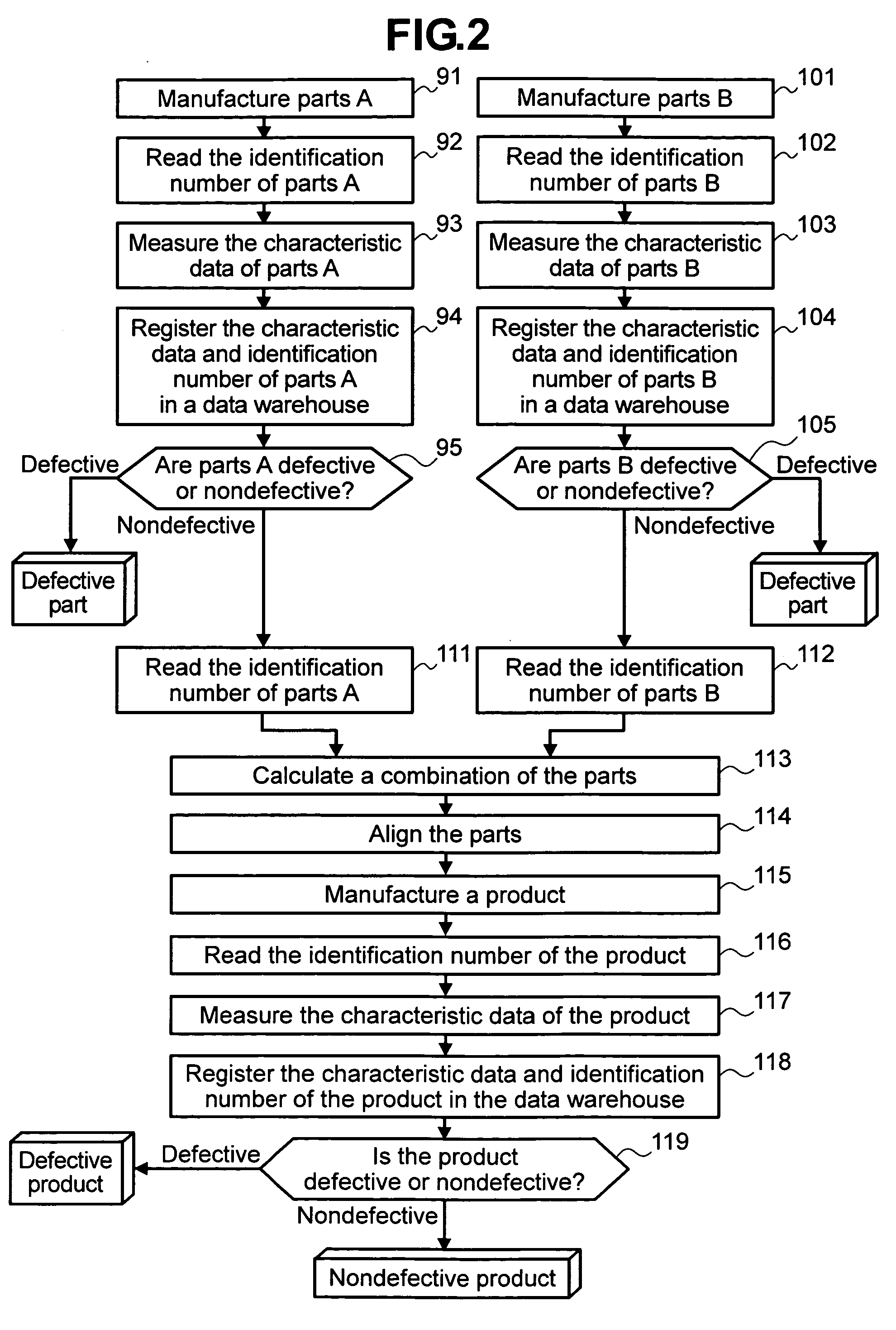
[0031]FIG. 2 is a diagram that shows an example of a flowchart of manufacturing process steps for products which are completed by manufacturing parts A and parts B independently and assembling the two kinds of parts as major components of a product. The parts A are manufactured in step 91, identification numbers (serial numbers) of the parts A are read in step 92, and characteristic data of the parts A is measured in step 93. In step 94, the identification numbers of the parts A that have been read in step 92 and the characteristic data of the parts A that has been measured in step 93 are registered in a data warehouse. Next, step 95 is executed to judge whether the parts A are defective or nondefective. If any parts A are judged to be nondefective in step 95, only those parts A are transferred for processing to step 111. Similarly to parts A, parts B are manufactured in step 101, identification numbers of the parts B are read in step 102, and characteristic data o...

second embodiment

(Second Embodiment)

[0054] Next, an embodiment of the present invention when applied to manufacturing a magnetic storage device will be described hereunder. A manufacturing process therefor will be first described using FIGS. 14 to 17. FIG. 14 shows an example of a flowchart of manufacturing process steps for a magnetic head which is a major component of the magnetic storage device. Magnetic heads can be roughly divided into upper magnetic heads for reading / writing data from an upper side of a disk, and lower magnetic heads for reading / writing data from a lower side of the disk. FIG. 14 shows an example of a flowchart of manufacturing process steps for an upper magnetic head. The upper magnetic head is manufactured in step 201, and an identification number of the upper magnetic head is read in step 202. Next, characteristic data of the upper magnetic head is measured in step 203. In step 204, the identification number that has been read in step 202, and the characteristic data that h...

third embodiment

(Third Embodiment)

[0059] Next, a description will be given of an embodiment which utilizes the present invention in a simplified fashion when, in the generalized product-manufacturing processes described in FIGS. 2 and 3, the number of products which have been completed as nondefectives in advance is too small for a nondefective product space to be calculated beforehand, as in a startup phase of mass production of a new device or in a test production phase thereof.

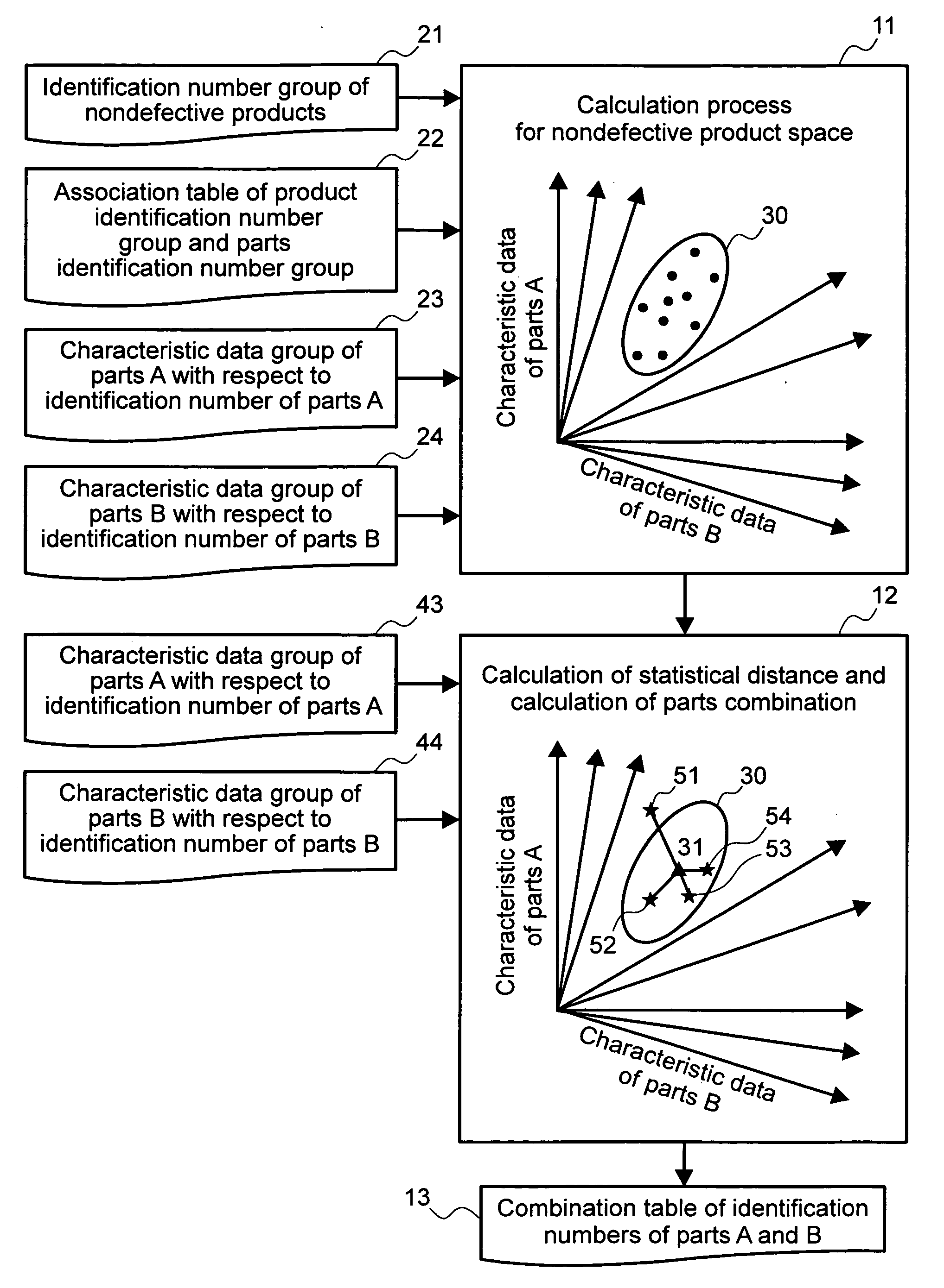
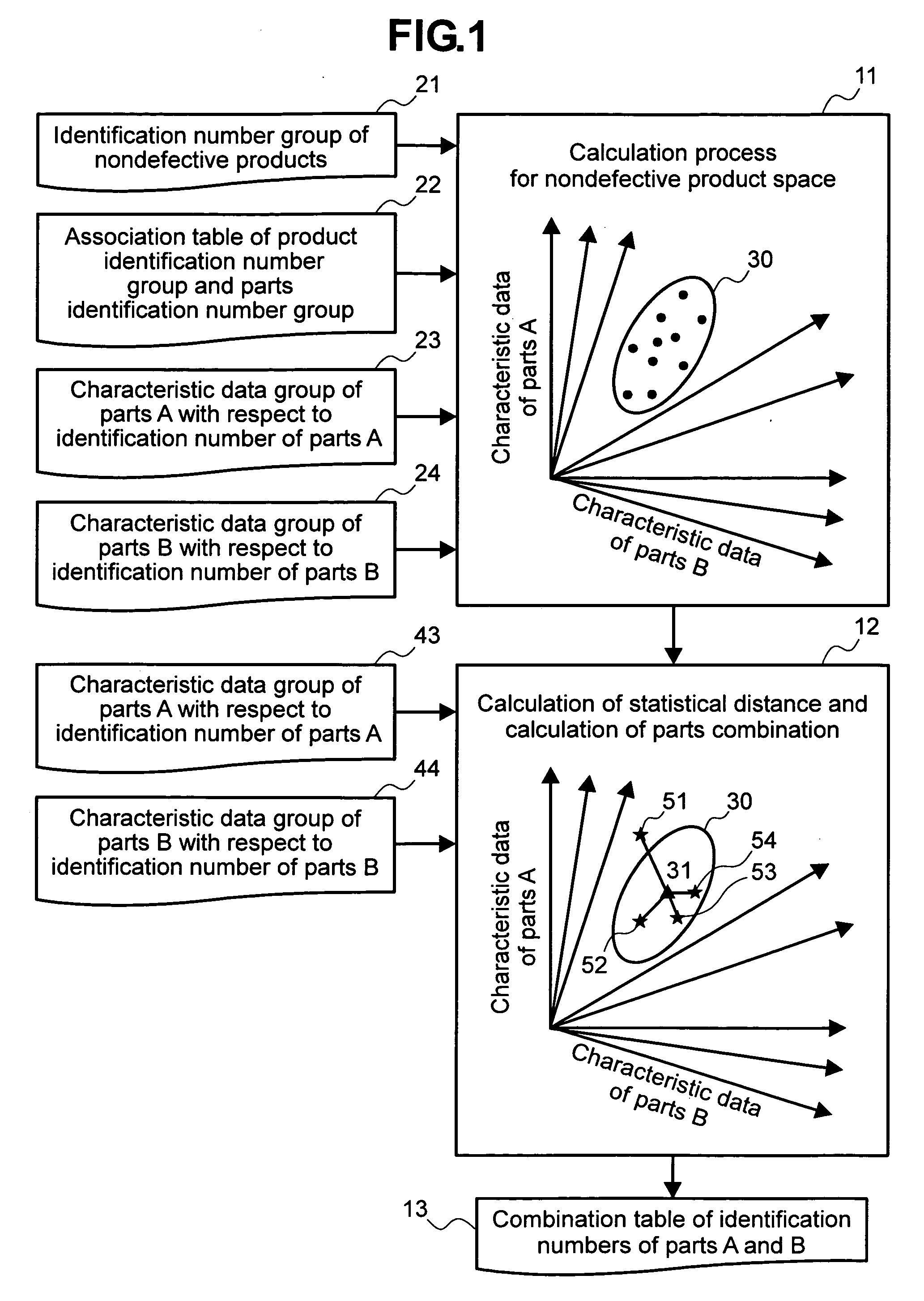
[0060]FIG. 19 shows an example of a processing procedure to be used to utilize the present invention in a simplified fashion. In a test production phase of a high-technology hardware product such as a magnetic storage device or multi-chip module, the number of products completed as nondefectives may be too small for processing to be executed in step 11. In such a case, as in step 11, mean values, standard deviations, and a correlation matrix are not calculated per (Formula 1), (Formula 2), and (Formula 5) respectively by ...


PUM


Abstract

This invention provides a parts-combining method that realizes production with high quality or a high yield for a product formed with a large number of parts, such as a magnetic storage device, multi-chip module, liquid-crystal display device, or printed-circuit board. A first step in this method is to enter an identification number group 21 of nondefective products whose manufacture has already been completed beforehand, an association table 22 of a product identification number group and a parts identification number group, a characteristic data group 23 of parts A with respect to identification numbers of the parts A and a characteristic data group 24 of parts B with respect to identification numbers of the parts B, and conduct a calculation process 11 for a nondefective product space. Next step is to, before a new product is manufactured, enter a characteristic data group 43 of parts A with respect to identification numbers of the parts A and a characteristic data group 44 of parts B with respect to identification numbers of the parts B, and conduct calculations on statistical distances and combinatorial computations between the parts as a calculation process 12. A final step is to output a combination table 13 that includes the identification numbers of the parts A and the identification numbers of the parts B.

Description

BACKGROUND OF THE INVENTION [0001] The present invention relates to a method of manufacturing a product formed with a large number of parts, such as a magnetic storage device, a multi-chip module, liquid-crystal display device, printed circuit board, automobile, or electrical household appliance. [0002] Manufacturing processes for a high-technology hardware product such as a magnetic storage device, multi-chip module, or liquid-crystal display device, generally consist of the parts-forming processes that require thin-flim forming, polishing, and other fine processing, and an assembly process for assembling completed parts. A magnetic storage device, for example, is manufactured by forming its major components, namely, a plurality of magnetic heads and disks in different parts-forming processes and then assembling each magnetic head and disk with a spindle motor, a frame, and other components in an assembly process to complete the device as a product. Also, a multi-chip module is man...

Claims


Application Information

Patent Timeline
IPC IPC(8): G06F19/00G05B19/418G06Q50/00G06Q50/04H01L21/02
CPCG06Q10/04G06Q50/04G06Q10/06395G06Q10/0631Y02P90/30
Inventor ONO, MAKOTONONAKA, YOICHIISHIBASHI, HISAYA
Owner HITACHI LTD
Why Eureka
Try Eureka