Integrated renewable energy system

a renewable energy system and compression ignition technology, applied in the direction of dynamo-electric machines, electrogenerative processes, non-fuel substance addition to fuel, etc., can solve the problem that the carbon dioxide produced by the combustion process would not directly contribute to global warming, and achieve the effect of fuel efficiency and reducing environmental pollution of the engin

Inactive Publication Date: 2007-01-04
H EMPOWER CORP
View PDF5 Cites 52 Cited by
  • Summary
  • Abstract
  • Description
  • Claims
  • Application Information

AI Technical Summary

Benefits of technology

[0011] The present invention seeks to provide ways of using a standard compression ignition engine as an integral part of a renewable energy system, so that the benefits associated with a diesel engine, i.e. its fuel efficiency and mechanical reliability, can be fully exploited whilst simultaneously reducing environmental pollution from the engine.

Problems solved by technology

For example, if compression ignition engines were able to efficiently burn non-fossil fuels, the carbon dioxide produced by the combustion process would not directly contribute towards global warming.

Method used


Image

  • Integrated renewable energy system
  • Integrated renewable energy system
  • Integrated renewable energy system

Examples


Embodiment Construction

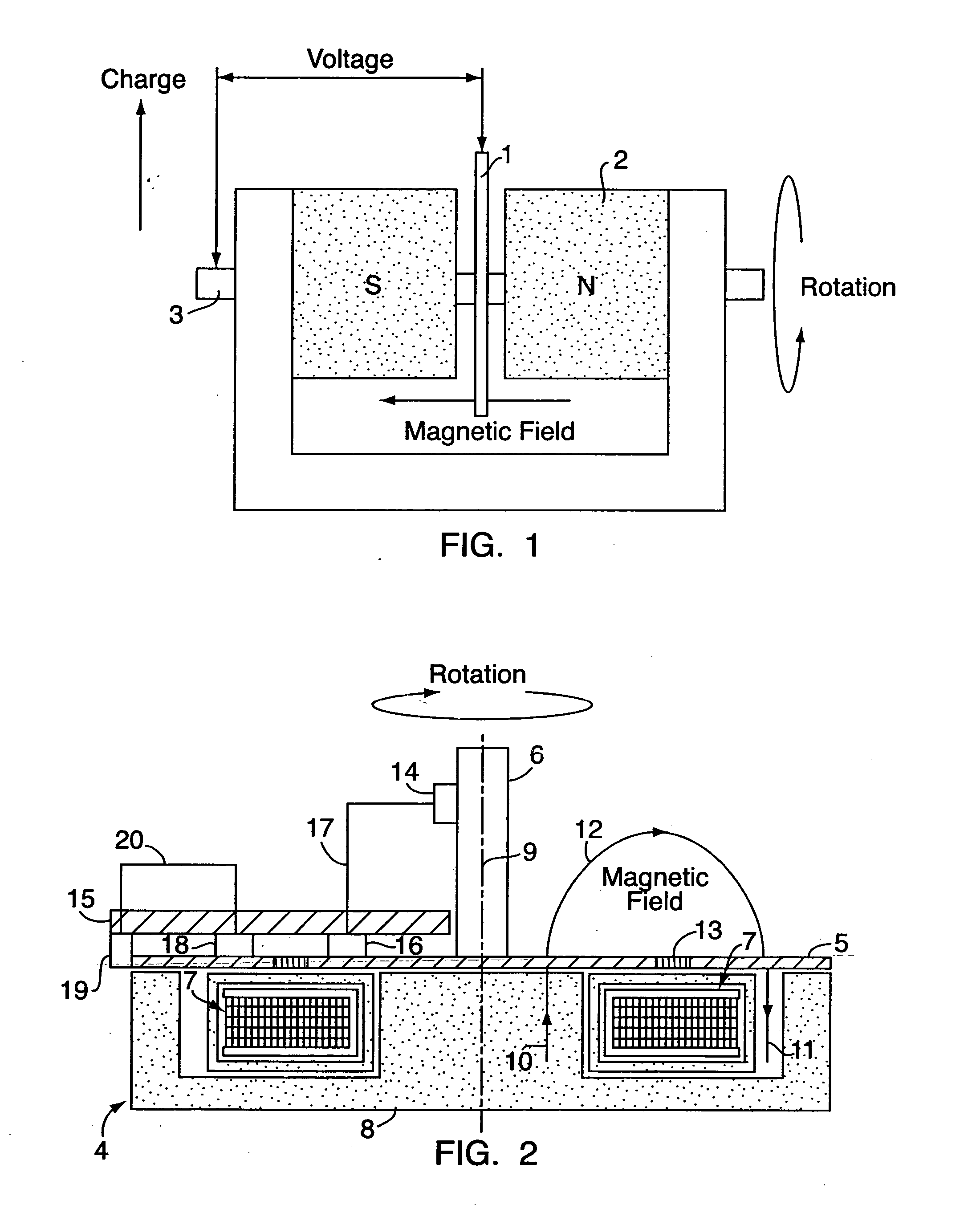
[0053] In FIG. 1, a shaft 3 runs through the center of both poles of a magnet 2, and in a manner whereby shaft 3 can freely rotate within the magnet 2. A metal disc 1 is fixed to shaft 3 and is spatially arranged so that the metal disc 1 is centrally located between the north and south poles of the magnet 2.

[0054] Rotation of shaft 3, by the application of an external rotating force, correspondingly rotates the metal disc 1 between the poles of the magnet 2, so that the disc intersects the magnetic field produced by the magnet.

[0055] Rotation of disc 1 in the magnetic field generates a voltage between the center of the disc and the rim of the disc. An electric charge, which can be collected by electrical contact brushes placed at the rim and at the center of the disc, is produced in disc 1.

[0056] The efficiency of a homopolar generator is greatly improved if an annular magnetic field, whose axis passes through the center of the drive shaft, is used in the system. When an annular ...


PUM


Abstract

A system and method are disclosed comprising coupling a compression ignition engine (17) to an AC electrical generator (18) and/or a DC hompolar generator (19), wherein the homopolar generator (19) produces an electric current which is used to electrolyse water into hydrogen and oxygen. The hydrogen from the water electrolysis process may be used as a renewable fuel, either in the form of a gaseous fuel or a reactant in a fuel cell. The oxygen from the water electrolysis unit (23) may be used to produce an oxygen enriched combustion atmosphere in the engine (17). The oxygen may optionally be used as a reactant, along with the hydrogen, in a fuel cell.

Description

CROSS REFERENCE TO RELATED APPLICATIONS [0001] This application is entitled to the benefit of and incorporates by reference essential subject matter disclosed in International Patent Application No. PCT / GB2004 / 001561 filed on Apr. 8, 2004 and Great Britain Patent Application No. 0308729.3 filed Apr. 15, 2003. FIELD OF THE INVENTION [0002] The present invention relates to a method of using a compression ignition engine in an integrated renewable energy system, whereby the engine is used to drive either an AC electrical generator to produce ‘green’ electricity for local use or a DC electrical generator to supply the electric current needed to electrolyse water into hydrogen and oxygen. BACKGROUND OF THE INVENTION [0003] Compression ignition engines are fuel efficient and diesel engines are therefore widely used for the generation of electricity as well as for transport purposes. Because diesel engines are also mechanically rugged and reliable, diesel engines are one of the most common...

Claims


Application Information

Patent Timeline
Patent Type & Authority Applications(United States)
IPC IPC(8): F01D15/10F02M25/12
CPCF02M25/12Y02T10/16Y02T10/121Y02E60/366Y02E60/36Y02T10/12Y02P20/133C25B1/04C25B5/00F01K25/12F01K27/00F02B65/00F03G7/00
Inventor MCNEIL, JOHN
Owner H EMPOWER CORP
Why Eureka
Try Eureka