
Electroplating method in the manufacture of the surface mount precision metal resistor

a technology of precision metal resistor and electroderoplating method, which is applied in the direction of resistor chip manufacture, resistor detail, resistor manufacturing, etc., to achieve the effect of reducing the total selling price, reducing the production cost, and increasing the output proportionally

Inactive Publication Date: 2007-01-04
HSIEH CHING HSIUNG
View PDF12 Cites 8 Cited by
  • Summary
  • Abstract
  • Description
  • Claims
  • Application Information

AI Technical Summary

Benefits of technology

[0003] The primary object of the present invention is to provide a chemical electroplating method to manufacture the surface mount precision metal resistor. By means of properly adjusting the current magnitude in electroplating process together with the rotational speed of the working resistor, the throughput can be proportionally expanded, thus, the productivity of the surface mount precision metal resistor can be substantially improved. It is not only enabled to meet the market monthly productivity demand but also having decreased the total selling price as well as having flexible adaptability in producing product of special specifications. That is the principal object of the present invention.

Problems solved by technology

But, local providers can only supply half of this demand so that importing (SMT Resistor) being still needed to offset the balance of that.

Method used


Image

  • Electroplating method in the manufacture of the surface mount precision metal resistor
  • Electroplating method in the manufacture of the surface mount precision metal resistor
  • Electroplating method in the manufacture of the surface mount precision metal resistor

Examples


Embodiment Construction

[0016] Following is the detailed description of the preferred specific embodiment of the present invention in association with illustrative figures.

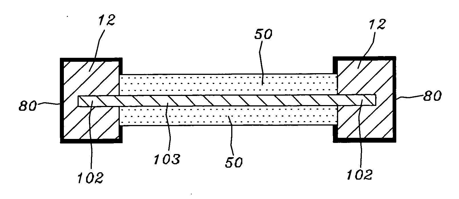
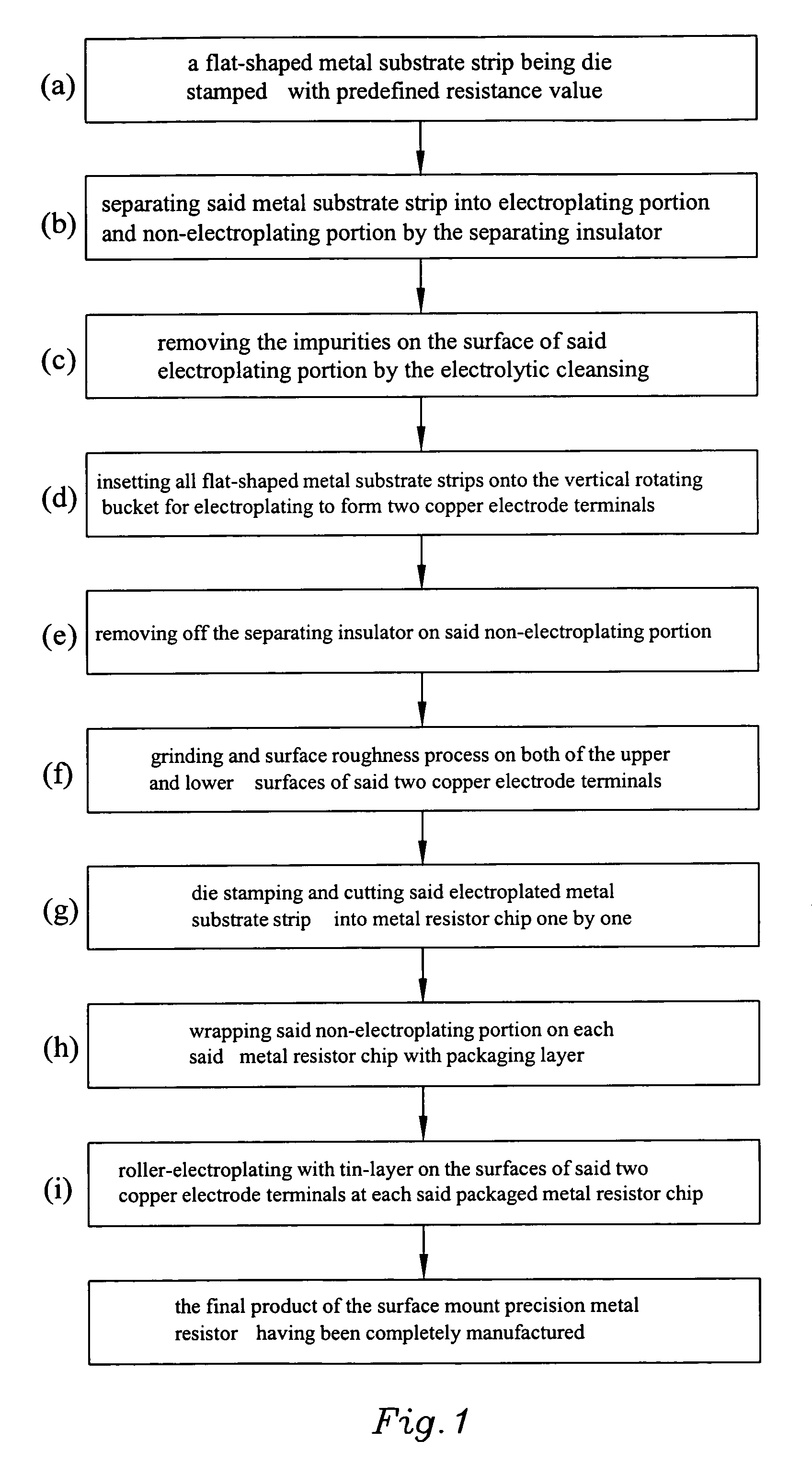
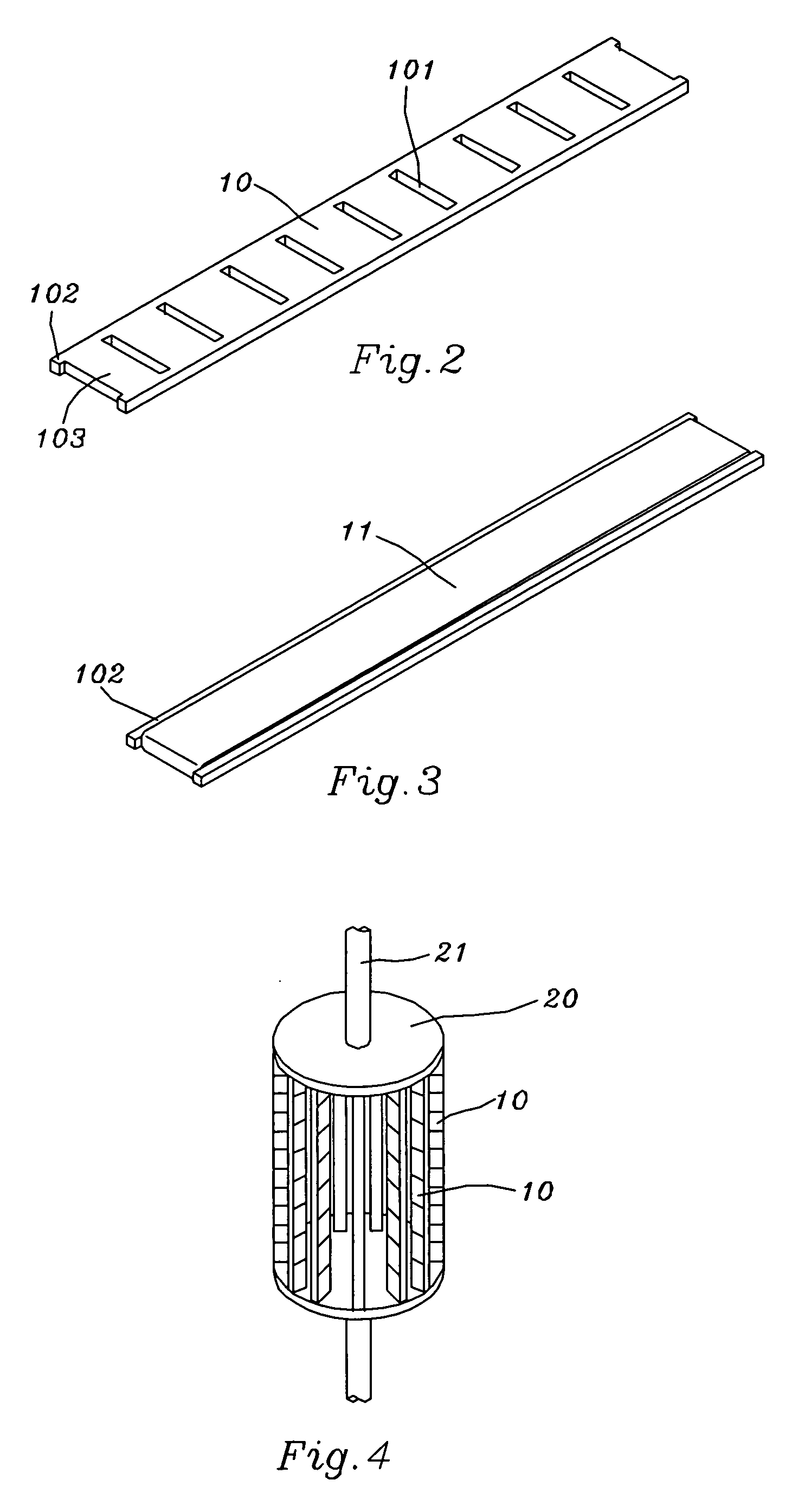
[0017] Refer to FIG. 1 through FIG. 11, the manufacturing steps of the electroplating method in the manufacture of the surface mount precision metal resistor are as below:

[0018] (a) According to the predefined resistance value (Ω), a flat-shaped metal substrate strip 10 with multiple rectangular holes 101 being die stamped in the manner of fixed interval such that its thickness being greater than 0.1 mm (as shown in the FIG. 2);

[0019] (b) By means of the acid-and-alkali-resisting adhesive tape 11 to serve as a separating insulator, completely wrapping the middle band of said metal substrate strip 10 to become as non-electroplating portion 103 and so that both of its lateral sides being become as electroplating portion 102 (as shown in the FIG. 3);

[0020] (c) Immerging said separating insulator wrapped metal substrate strip 10 into the...


PUM


Abstract

The present invention relates to an electroplating method in the manufacture of the surface mount precision metal resistor, the manufacturing steps are as below: a flat-shaped metal substrate strip being die stamped with predefined resistance value; separating said metal substrate strip into electroplating portion and non-electroplating portion by the separating insulator; removing the impurities on the surface of said electroplating portion by the electrolytic cleansing; insetting all flat-shaped metal substrate strips onto the vertical rotating bucket for electroplating to form two copper electrode terminals; removing off the separating insulator on said non-electroplating portion; grinding and surface roughness process on both of the upper and lower surfaces of said two copper electrode terminals; die stamping and cutting said electroplated metal substrate strip into metal resistor chip one by one; wrapping said non-electroplating portion on each said metal resistor chip with packaging layer; and roller-electroplating with tin-layer on the surfaces of said two copper electrode terminals at each said packaged metal resistor chip, thus the final product of the surface mount precision metal resistor having been completely manufactured.

Description

FIELD OF THE PRESENT INVENTION [0001] The present invention relates to an electroplating method in the manufacture of the surface mount precision metal resistor, more particularly a chemical electroplating method to manufacture the surface mount precision metal resistor. By means of properly adjusting the current magnitude in electroplating process together with the rotational speed of the working resistor, the throughput can be proportionally expanded, thus, the productivity of the surface mount precision metal resistor can be substantially improved. BACKRGROUND OF THE PRESENT INVENTION [0002] Due to the popularity of the global 3C electronic product and the requirement trend of lightweight, thin and small size in design, the demand quantity of the (SMT Resistor) is constantly increased. Currently, the monthly demand of the (SMT Resistor) in Taiwan exceeds 50 millions. But, local providers can only supply half of this demand so that importing (SMT Resistor) being still needed to of...

Claims


Application Information

Patent Timeline
IPC IPC(8): H01C1/012
CPCH01C7/001H01C7/06H01C17/281H01C17/02H01C17/006H01C1/012
Inventor HSIEH, CHING HSIUNG
Owner HSIEH CHING HSIUNG
Learn More