Antenna device, wireless communication apparatus using the same, and control method of controlling wireless communication apparatus

a wireless communication apparatus and antenna technology, applied in the direction of antennas, electrical devices, antenna arrays, etc., can solve the problems of difficult communication with any destination, interference with the other wireless communication apparatus that communicates, antenna devices, etc., and achieve the optimal condition of any transmission performance, large-scale and/or expensive wireless communication apparatus

Inactive Publication Date: 2007-01-04
SONY CORP
View PDF6 Cites 150 Cited by
  • Summary
  • Abstract
  • Description
  • Claims
  • Application Information

AI Technical Summary

Benefits of technology

[0035] Further, setting the direct-current biased voltage applied across each of the control electrodes connected with the semi-conductive antenna bodies in the antenna device allows a directional antenna to be formed by combining a waveguide and a reflector which are formed of the semi-conductive antenna bodies that have been switched to their conductive states or their insulated states. This enables any feedback setting on the direct-current biased voltage applied across the control electrodes to be implemented by guiding any wireless communication condition to a wireless communication apparatus of a destined node.
[0036] Thus, by the embodiment of the control method according to the invention, it is possible to adjust directivity / omnidirectivity, radiated polarization and radiation direction of the antenna device to desired ones without making the wireless communication apparatus large-scaled and / or expensive, thereby enabling optimal condition of any transmission performance to a wireless communication apparatus of a destined node to be maintained. This allows any wireless communication according to CSMA / CA or the like to be performed.

Problems solved by technology

Under the wireless LAN environment in which plural wireless communication apparatuses are present, however, it may be difficult to communicate with any destination after having sensed a carrier when using a directional antenna.
Thus, irrespective of a case where any other than the wireless communication apparatus that wants to communicate any destination communicates, this wireless communication apparatus can transmit a radio wave with it failing to sense a carrier, so that it may interfere with the other wireless communication apparatus that communicates.
This causes an antenna device and a wireless communication apparatus to be made large-scaled and / or to be made expensive.

Method used


Image

  • Antenna device, wireless communication apparatus using the same, and control method of controlling wireless communication apparatus
  • Antenna device, wireless communication apparatus using the same, and control method of controlling wireless communication apparatus
  • Antenna device, wireless communication apparatus using the same, and control method of controlling wireless communication apparatus

Examples


first embodiment

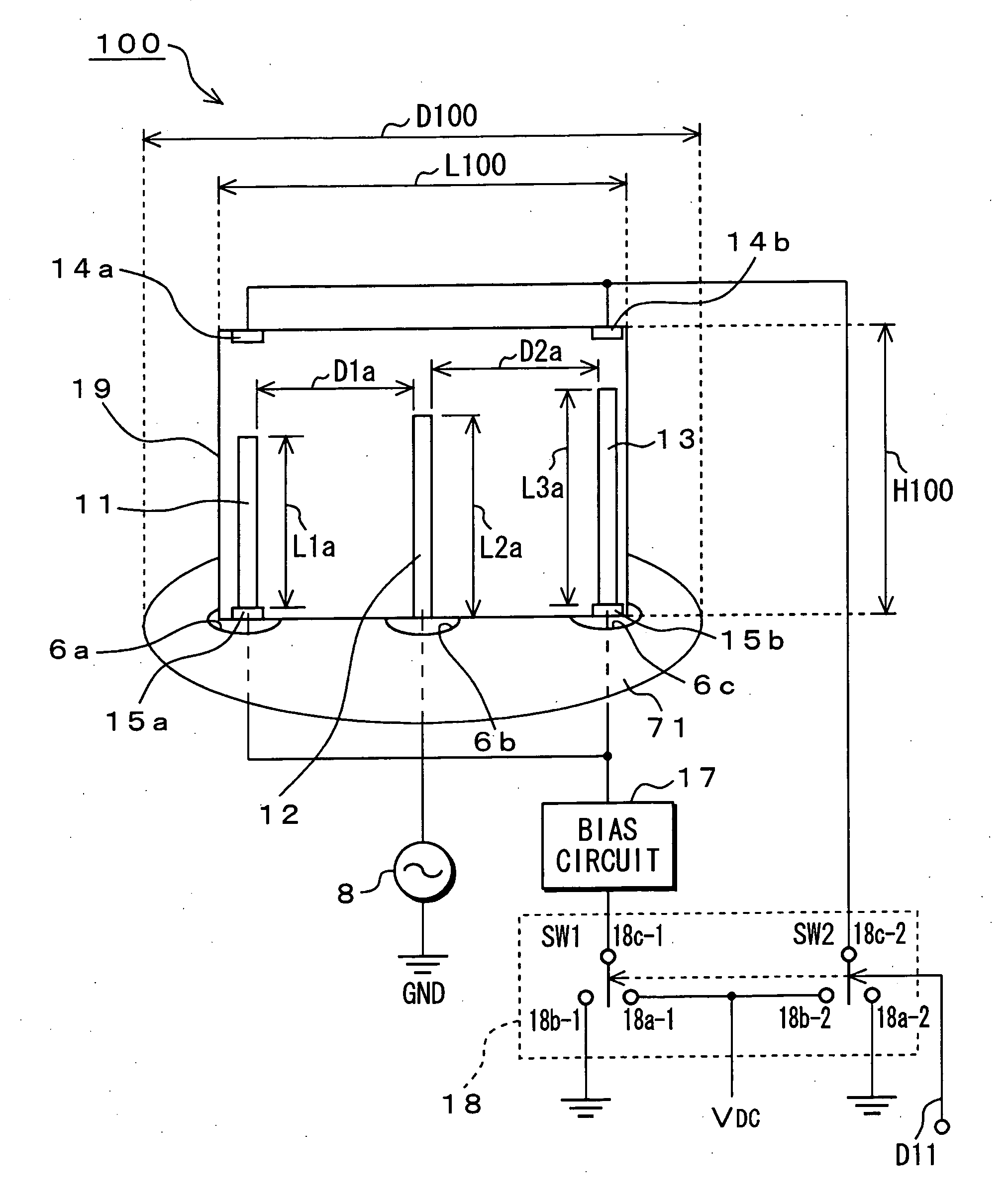
[0059]FIG. 3 illustrates a configuration of a Yagi antenna device 100 of monopole type according to the invention.

[0060] The Yagi antenna device 100 shown in FIG. 3 has a base disk 71 as a base plate for grounding, and a dielectric substrate 19 having antenna bodies. The base disk 71 is constituted of a printed board having a diameter D100. The base disk 71 has at predetermined positions three openings 6a, 6b, 6c through which control wires are passed.

[0061] The dielectric substrate 19 is positioned on the base disk 71 with them being intersected with each other. The dielectric substrate 19 has, for example, a height of H100 and a length of L100. The dielectric substrate 19 is made of solid electrolyte material selected from silicon gel, acrylonitrile gel, polysaccharide polymer and the like, which are used for a lithium ion battery or the like. The solid electrolyte material is subject to anion movement. The antenna bodies include a parasitic antenna element 11 for a waveguide, wh...

second embodiment

[0097]FIG. 8 illustrates a configuration of a Yagi antenna device 200 of slot type according to the invention. In this embodiment, the Yagi antenna device 200 has a conductive antenna pattern (hereinafter, referred to as “a base plate 72”) on a dielectric substrate 29. The conductive base plate 72 has two slots (hereinafter, referred to as “parasitic antenna slots 16a, 16c”) that expose two semi-conductive parasitic antenna elements 21, 23, respectively, and one slot (hereinafter, referred to as “an excited antenna slot 16b”) acting as an excited antenna element 22, which is arranged with it being positioned between the two parasitic antenna slots 16a, 16c with predetermined distances D1b, D2b. The excited antenna slot 16b is fed. Forward or reverse biased voltage is applied across each of the control electrodes 25a, 25b connected with the parasitic antenna elements 21, 23 in the parasitic antenna slots 16a, 16c.

[0098] In the Yagi antenna device 200, the dielectric substrate 29 hav...

third embodiment

[0127]FIG. 11 illustrates a configuration of an antenna device 300 with a polarization switch function according to the invention.

[0128] In this embodiment, the antenna device 300 has the polarization switch function in addition to the switch function of directivity / omnidirectivity by the Yagi antennas of monopole type described as the first embodiment of the invention and the slot type described as the second embodiment of the invention. In this embodiment, the antenna device 300 has a semi-conductive antenna pattern (hereinafter, referred to as “a base plate 73”) on a dielectric substrate 39. The base plate 73 made of semi-conductive plastic material has two slots (hereinafter, referred to as “parasitic antenna slots 26b, 26c”) that respectively expose two parasitic antenna elements 31, 33 made of semi-conductive plastic material, and one slot (hereinafter, referred to as “an excited antenna slot 26a”) that exposes an excited antenna element 32 made of semi-conductive plastic mate...


PUM


Abstract

An antenna device has semi-conductive antenna bodies each having a predetermined length, which are positioned on a dielectric substrate, and control electrodes that are respectively connected with the semi-conductive antenna bodies. Direct-current biased voltage applied across each of the control electrodes is controlled to switch each of the antenna bodies between their insulation state and their conductive state.

Description

CROSS REFERENCE TO RELATED APPLICATION [0001] The present invention contains subject matters related to Japanese Patent Application No. JP 2005-192730 filed in the Japanese Patent Office on Jun. 30, 2005, the entire contents of which being incorporated herein by reference. BACKGROUND OF THE INVENTION [0002] 1. Field of the Invention [0003] The present invention relates to an antenna device, a wireless communication apparatus using the antenna device, a control method of controlling the wireless communication apparatus, a program product therefor, and a computer-readable storage medium therefor. [0004] 2. Description of Related Art [0005] Recently, a wireless communication function has been often implemented in an information processing apparatus such as a personal computer, a communication terminal such as a mobile phone and a personal digital assistance (PDA), and any various kinds of consumer appliances such as an audio instrument, video equipment, a camera, a printer, and an ente...

Claims


Application Information

Patent Timeline
Patent Type & Authority Applications(United States)
IPC IPC(8): H01Q21/00
CPCH01Q19/32H01Q3/44
Inventor HIRABAYASHI, TAKAYUKI
Owner SONY CORP
Why Eureka
Try Eureka