Fuel vapor management for stored fuel using floating particles

Inactive Publication Date: 2007-01-11
FORD GLOBAL TECH LLC
View PDF12 Cites 8 Cited by
  • Summary
  • Abstract
  • Description
  • Claims
  • Application Information

AI Technical Summary

Benefits of technology

[0006] The present invention includes a system, method, and article of manufacture for reducing the rate of fuel vapor formation within a fuel storage tank via a plurality of discrete floating particles or elements to reduce exposed evaporative surface area of fuel in the tank. The discrete particles conform to a changing fuel tank cross-section as fuel level changes. The elements or particles may have a simple spherical geometry and/or have a two- or three-dimensional self-tessellating geometry, such as a cube, prismatic triangle, or prismatic hexagon to facilitate formation of a single or multi-layer liquid-vapor barrier and be made or coated with a material that resists fuel wetting and degradation, such as a highly fluorinated polymer including polytetrafluoroethylene (Teflon). In various embodiments of the invention, the particles have a geometry including an apex and a weighted base to provide a desired orientation while floating on or near the surface of the fuel to facilitate shedding of liquid fuel. Representative geometries include a pyramid, cone, or triangular prism, for example. Particles having different

Problems solved by technology

Modern automotive fuel systems have a complex system that typically includes a vapor recovery canister to capture and subsequently purge fuel vapors.
While this technology has evolved to an efficient and effective system for managing fuel vapor in vehicles powered by a conventional internal combustion (IC) engine, it is not readily amenable for use in hybrid electric vehicles that utilize an IC engine and an electric moto

Method used


Image

  • Fuel vapor management for stored fuel using floating particles
  • Fuel vapor management for stored fuel using floating particles
  • Fuel vapor management for stored fuel using floating particles

Examples


Example

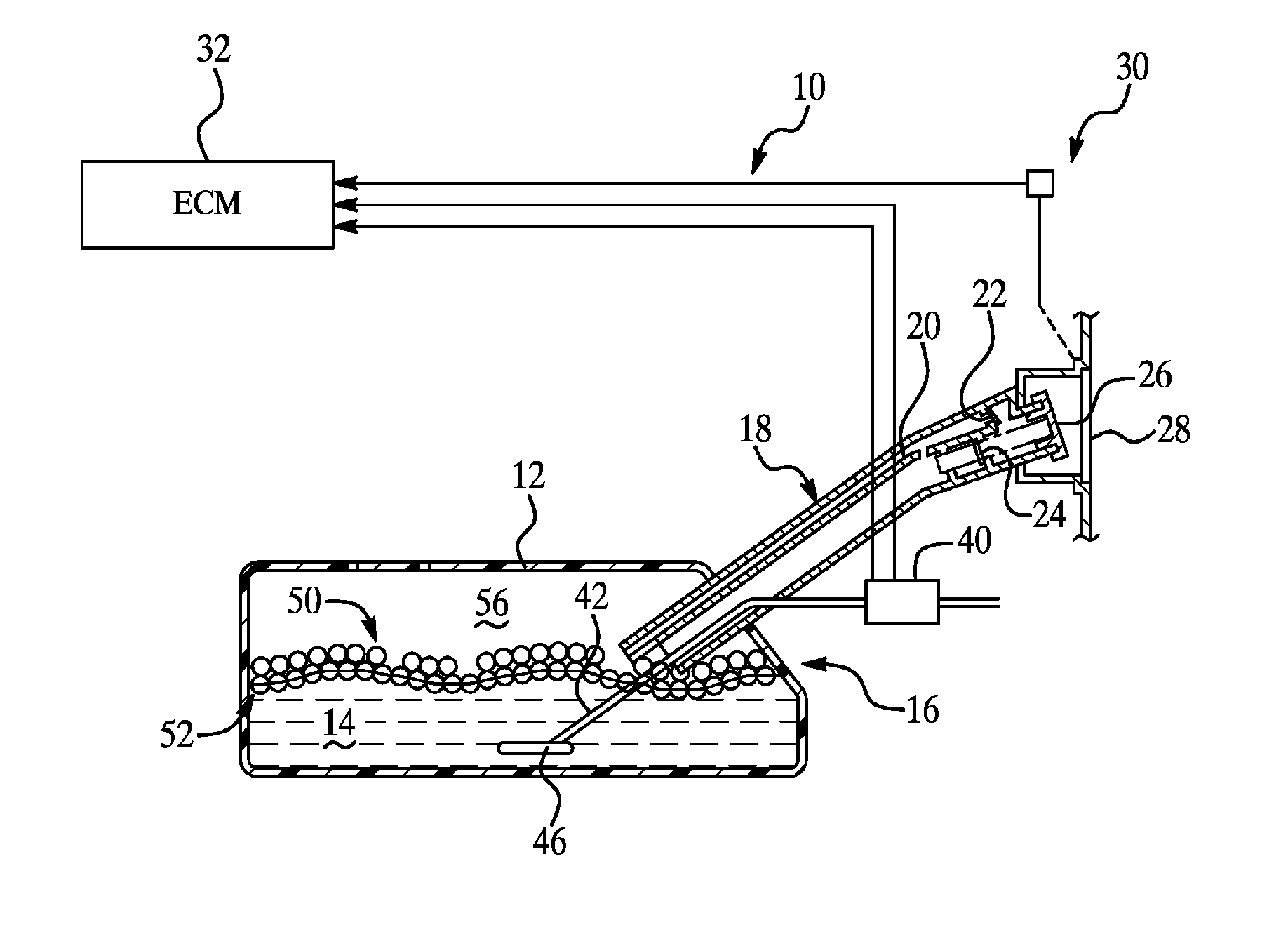
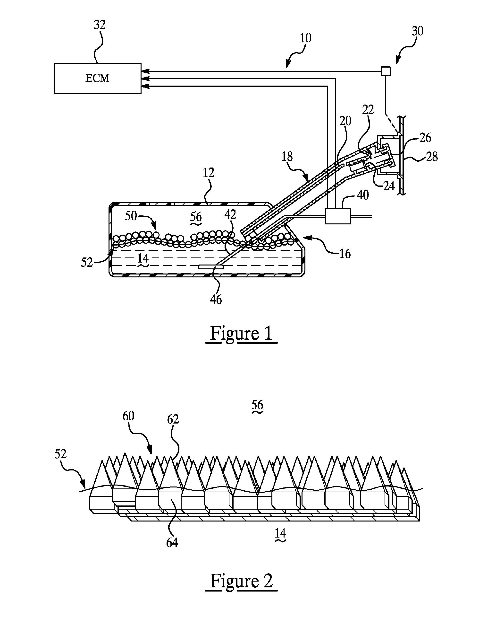
[0015]FIG. 1 is a partial cross-section of a representative fuel system illustrating a system or method for reducing the rate of fuel vapor formation according to one embodiment of the present invention. Although the present invention is illustrated and described with respect to a representative automotive fuel system 10, those of ordinary skill in the art will recognize that the present invention may be used in a number of diverse applications that include a volatile liquid stored in a rigid or semi-rigid storage tank to reduce vapor formation rate by reducing exposed evaporative surface area.

[0016] Representative fuel system 10 includes a semi-rigid or rigid container or tank 12 adapted for holding liquid fuel 14. Tank 12 may have a varying cross-section to maximize fuel storage capacity while accommodating packaging constraints for a particular application. Fuel filling tube 18 may include a vapor recirculation channel 20 and vent valve 22 to manage vapor generation during fuel ...


PUM


Abstract

A system, method, and article of manufacture for reducing the rate of fuel vapor formation within a fuel storage tank include a plurality of discrete independent floating particles or elements to reduce exposed evaporative surface area of fuel in the fuel storage tank while conforming to a changing fuel tank cross-section as fuel level changes. The elements or particles may have a self-tessellating geometry to facilitate formation of a single or multi-layer barrier or cover and be made or coated with a material that resists fuel wetting and degradation, such as a highly fluorinated polymer including polytetrafluoroethylene.

Description

BACKGROUND OF THE INVENTION [0001] 1. Field of the Invention [0002] The present invention relates to systems and methods for reducing fuel vapor produced by stored fuel. [0003] 2. Background Art [0004] Evaporation of fuel in a fuel tank produces fuel vapor that must be managed to reduce or eliminate releasing of the vapor to the atmosphere. Modern automotive fuel systems have a complex system that typically includes a vapor recovery canister to capture and subsequently purge fuel vapors. While this technology has evolved to an efficient and effective system for managing fuel vapor in vehicles powered by a conventional internal combustion (IC) engine, it is not readily amenable for use in hybrid electric vehicles that utilize an IC engine and an electric motor, particularly during periods when the vehicle is operating with the IC engine off. The IC engine in a hybrid electric vehicle may run only 50% or less of a typical driving cycle yet the amount of fuel vapor that needs to be man...

Claims


Application Information

Patent Timeline
IPC IPC(8): F02M37/20
CPCF02M25/089F02M2025/0845F02M37/20F02M37/0082
Inventor SCHONDORF, STEVENGABOURY, SCOTTSTEPHAN, CRAIG
Owner FORD GLOBAL TECH LLC
Why Eureka
Try Eureka