Actuator device, liquid-jet head and liquid-jet apparatus

a technology of liquid-jet head and actuator, which is applied in the direction of device material selection, inking apparatus, generator/motor, etc., can solve the problems of low manufacturing efficiency, inability to direct the lower electrode to the (100) orientation, and difficulty in causing the lower electrode to have the orientation

Inactive Publication Date: 2007-01-11
SEIKO EPSON CORP
View PDF19 Cites 32 Cited by
  • Summary
  • Abstract
  • Description
  • Claims
  • Application Information

AI Technical Summary

Benefits of technology

[0016] An advantage of some aspects of the invention is to provide: an actuator device including a piezoelectric layer formed of crystals whose fluctuations in a polarization direction are suppressed, and which are in an undistorted state; and a liquid-jet head and a liquid-jet apparatus each including the actuator device as a driving source for ejecting liquid droplets.

Problems solved by technology

Although, by using the single crystal silicon substrate whose plane orientation is the (110) orientation, an attempt to cause the piezoelectric layer to have the (100) orientation has been made by forming the silicon oxide layer on the surface of one side of the single crystal silicon substrate, and then forming the lower electrode of the (100) orientation on the silicon oxide layer, it has been very difficult to cause the lower electrode to have the (100) orientation.
However, even if titanium serving as orientation control of the piezoelectric layer is provided, the piezoelectric layer is formed through free growth, whereby there exists a problem that the plane orientation thereof cannot be completely the (100) orientation because fluctuations in orientation occur in the piezoelectric layer.
Additionally, since strict process management is required in order to form titanium on the lower electrode, manufacturing processes become complicated, whereby there exists a problem that a manufacturing efficiency is low.
Note that, obviously, problems of these kinds occur not only in ink-jet recording heads, but also in other liquid-jet heads.

Method used


Image

  • Actuator device, liquid-jet head and liquid-jet apparatus
  • Actuator device, liquid-jet head and liquid-jet apparatus
  • Actuator device, liquid-jet head and liquid-jet apparatus

Examples


Embodiment Construction

[0043] Hereinbelow, the invention will be described in detail based on an embodiment.

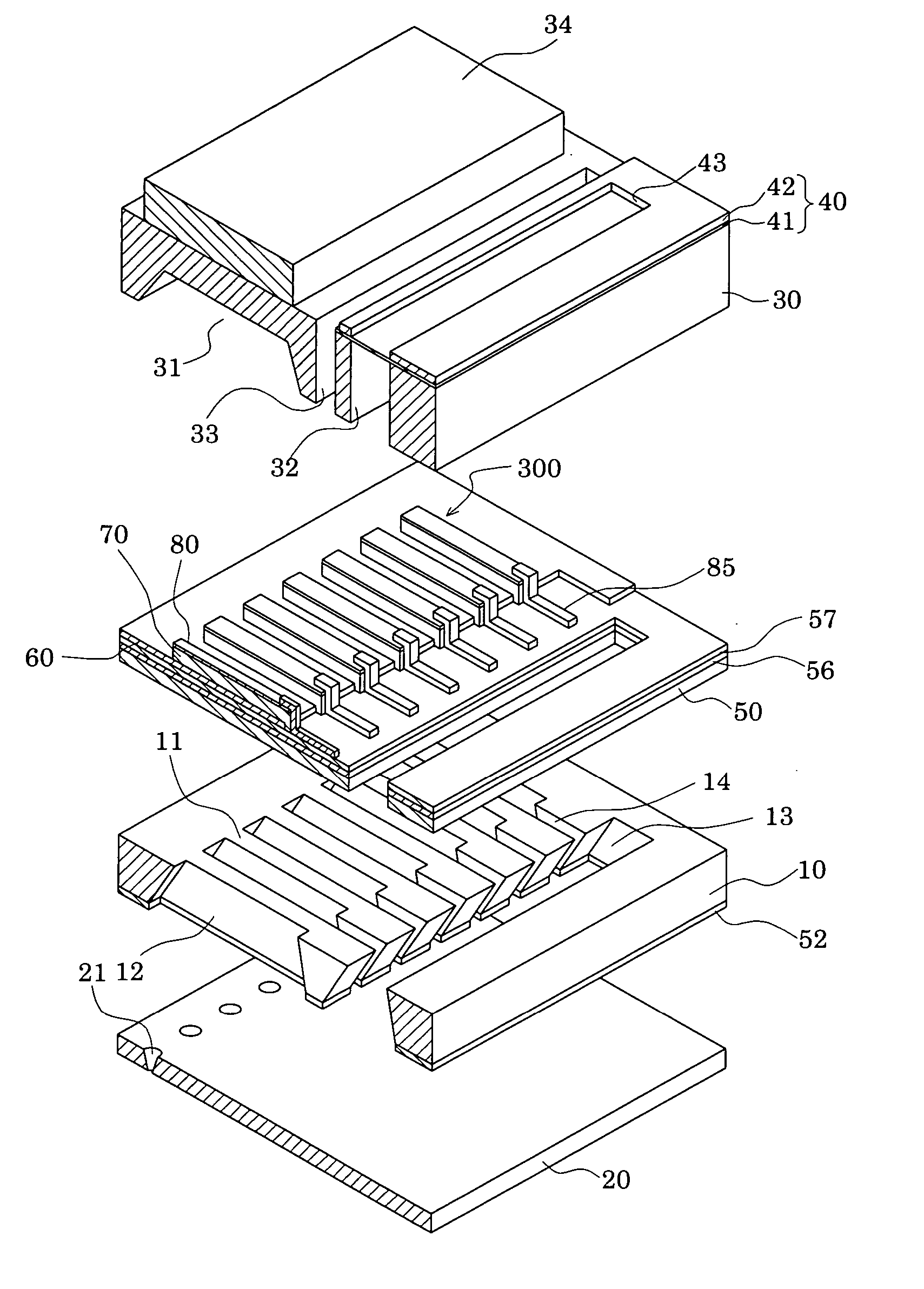
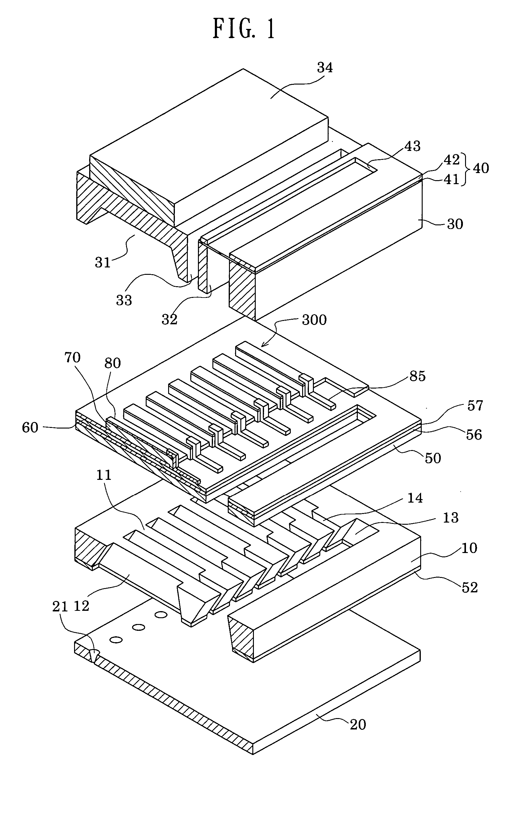
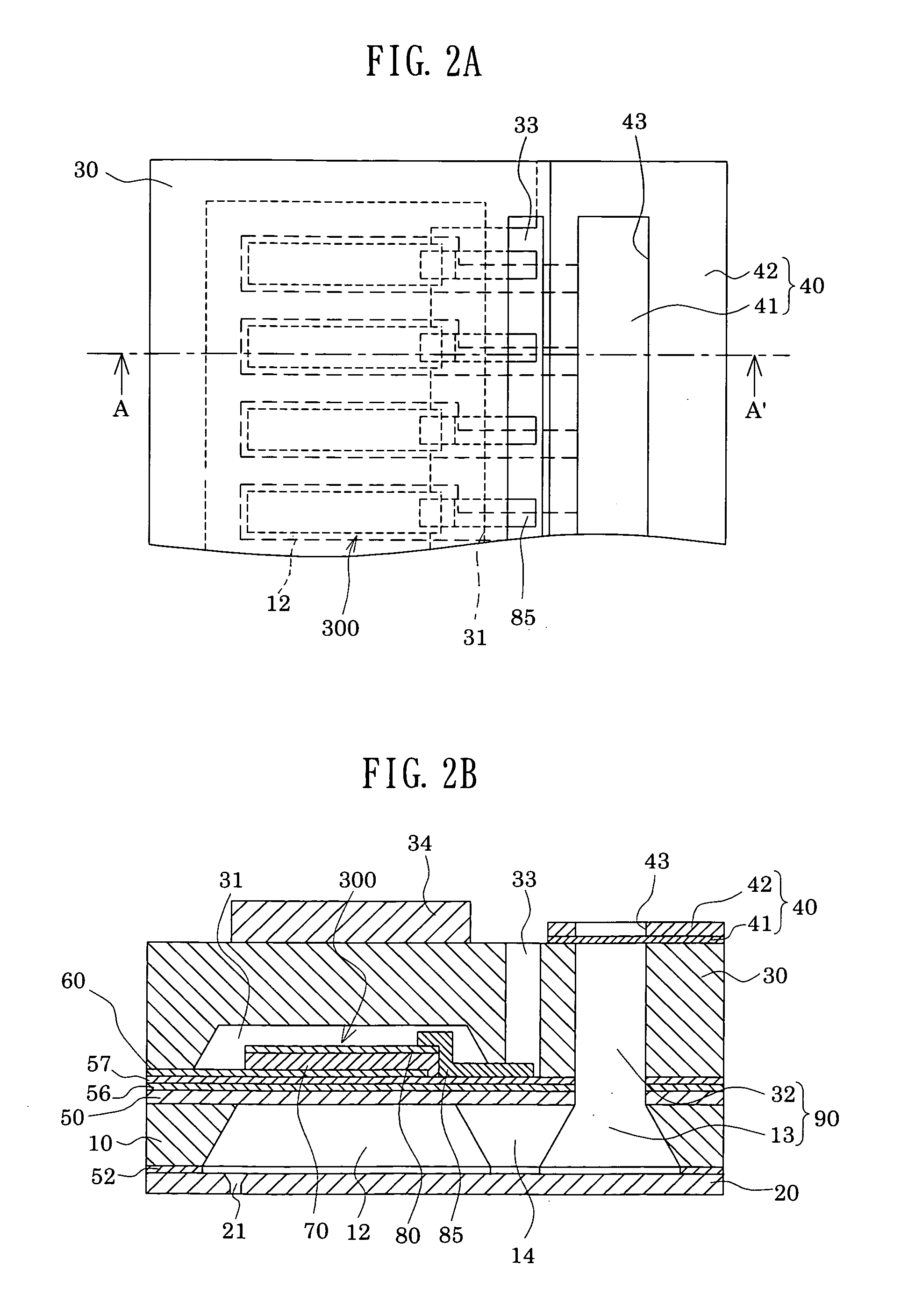
[0044]FIG. 1 is an exploded disassembled perspective view showing an ink-jet recording head which is one example of a liquid-jet head according to one embodiment. FIGS. 2A and 2B are a plane view of FIG. 1, and a cross-sectional view taken along an A-A′ line thereof, respectively.

[0045] A passage-forming substrate 10 is made of single crystal silicon having the (110) plane orientation in this embodiment, and on a surface of one side thereof, an elastic film 50 having a thickness between 0.5 and 2 μm is formed. Note that, in this embodiment, this elastic film 50 is an amorphous (non-crystal) film made of silicon oxide formed by thermally oxidizing the passage-forming substrate 10 which is a single crystal silicon substrate, and the elastic film 50 has a smooth surface state directly maintaining a surface state of the passage-forming substrate 10.

[0046] On this passage-forming substrate 10, by anis...


PUM


Abstract

An actuator device includes: a layer provided on a single crystal silicon (Si) substrate, and made of silicon dioxide (SiO2); at least one buffer layer provided on the layer made of silicon dioxide (SiO2); a base layer provided on the buffer layer, and made of lanthanum nickel oxide (LNO) having the (100) plane orientation; and a piezoelectric element. The piezoelectric element includes: a lower electrode provided on the base layer, and made of platinum (Pt) having the (100) plane orientation; a piezoelectric layer made of a ferroelectric layer whose plane orientation is the (100) orientation, the piezoelectric layer formed on the lower electrode by epitaxial growth where a crystal system of at least one kind selected from a group consisting of a tetragonal system, a monoclinic system and a rhombohedral system dominates the other crystal systems; and an upper electrode provided on the piezoelectric layer.

Description

[0001] The entire disclosure of Japanese Patent Application Nos. 2005-200923 filed Jul. 8, 2005 and 2006-153922 filed Jun. 1, 2006 is expressly incorporated by reference herein. BACKGROUND [0002] 1. Technical Field [0003] The present invention relates to: an actuator device using piezoelectric elements including a piezoelectric layer whose fluctuations in a polarization direction are suppressed; and a liquid-jet head and a liquid-jet apparatus each including the actuator device as a driving source for ejecting liquid droplets. [0004] 2. Related Art [0005] An actuator device including piezoelectric elements caused to displace by application of a voltage is mounted, for example, on a liquid-jet head or the like, which ejects liquid droplets. As a liquid-jet apparatus including the liquid-jet head as described above, there can be cited, for example, an ink-jet recording apparatus including an ink-jet recording head provided with: a plurality of pressure generating chambers which genera...

Claims


Application Information

Patent Timeline
Patent Type & Authority Applications(United States)
IPC IPC(8): H01L41/187B41J2/045B41J2/055B41J2/135B41J2/14B41J2/145B41J2/16H01L41/09H01L41/18H02N2/00
CPCB41J2/14233B41J2002/14241B41J2002/14419B41J2202/03H01L41/319H01L41/0973H01L41/1876H01L41/318B41J2202/20H10N30/2047H10N30/8554H10N30/078H10N30/079H10N30/80H10N30/20
Inventor TAKABE, MOTOKISUMI, KOJIYOKOYAMA, NAOTO
Owner SEIKO EPSON CORP
Why Eureka
Try Eureka