Power amplifier and transmitter

a power amplifier and transmitter technology, applied in the field of power amplifiers, can solve the problems of low power efficiency, low load resistance, and difficult to realize high efficiency with most conventional power amplifiers, and achieve the effect of simple structure and high power efficiency

Inactive Publication Date: 2007-01-11
HITACHI LTD
View PDF3 Cites 55 Cited by
  • Summary
  • Abstract
  • Description
  • Claims
  • Application Information

AI Technical Summary

Benefits of technology

[0029] As described above, the present invention provides the technique for realizing a broad-band Doherty type amplifier with a simple structure which can be applied to a broad carrier band or a plurality of carrier bands, and a transmitter using the same. In addition, in a system in which transmission lines needed for a high frequency band are partially shunted with one or a plurality of capacitors in a lower fre...

Problems solved by technology

Hence, high efficiency is difficult to realize with most conventional power amplifiers.
Thus, when viewed from the carrier amplifier side, the load resistance appears to increase, leading to lower power efficiency.
Although the load voltage increases with a current supplied from the peak amplifier, ho...

Method used


Image

  • Power amplifier and transmitter
  • Power amplifier and transmitter
  • Power amplifier and transmitter

Examples


first embodiment

[0055] Next, a first embodiment according to the present invention will be described in detail with reference to FIGS. 3 to 6.

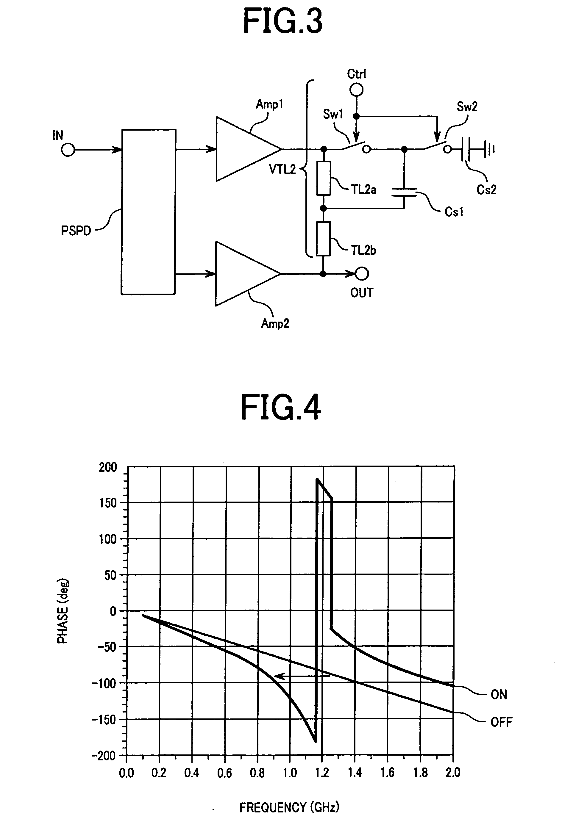
[0056]FIG. 3 is a circuit diagram of a Doherty type amplifier of the first embodiment of the present invention.

[0057]FIG. 4 is a graphical representation showing a relationship between frequency and phase delay of the output power combiner of the Doherty type amplifier of the first embodiment of the present invention.

[0058]FIG. 5 is an equivalent circuit diagram of a transmission line.

[0059]FIG. 6 is an equivalent circuit diagram of a variable electric length circuit of the first embodiment of the present invention.

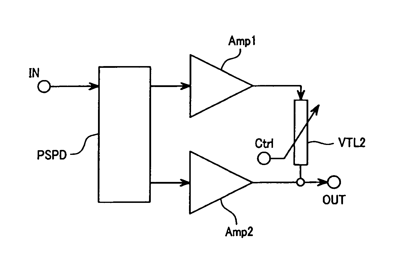
[0060] The first embodiment shows a more concrete circuit for realizing the variable electric length power combiner VTL2 shown in FIG. 1. The carrier amplifier Amp1, the peak amplifier Amp2, and the 90-degree phase-shift power divider PSPD are the same as those in the outline described with reference to FIG. 1.

[0061] Here, it is assumed that ...

second embodiment

[0068] Next, a second embodiment according to the present invention will be descried in detail with reference FIG. 7.

[0069]FIG. 7 is a circuit diagram of a Doherty type amplifier of the second embodiment of the present invention.

[0070] In the second embodiment, the switches of the first embodiment are replaced with FET elements, respectively.

[0071] The carrier amplifier Amp1 of the Doherty type amplifier of the second embodiment of the present invention, as shown in FIG. 7, is constituted by an FET element Mc and a dc-block capacitor Cc1. A drain terminal, a source terminal, and a gate terminal of the FET element Mc are connected to a power source voltage terminal Vdc, a ground, and a bias voltage terminal Vgc, respectively. The dc-block capacitor Cc1 is connected between the 90-degree phase-shift power divider PSPD and the gate terminal of the FET element Mc.

[0072] The peak amplifier Amp2 is constituted by an FET element Mp and a dc-block capacitor Cp1. A drain terminal, a sour...

third embodiment

[0079] Next, a third embodiment according to the present invention will be described in detail with reference to FIG. 8.

[0080]FIG. 8 is a circuit diagram of a Doherty type amplifier of the third embodiment of the present invention.

[0081] In the third embodiment, the carrier amplifier Amp1 and the peak amplifier Amp2 of the second embodiment are constituted by bipolar elements instead of FET elements.

[0082] The carrier amplifier Amp1 of the third embodiment, as shown in FIG. 8, is constituted by a bipolar element Bc and the dc-block capacitor Cc1. A collector terminal, an emitter terminal, and a base terminal of the bipolar element Bc are connected to a power source voltage terminal Vdc, a ground, and a bias voltage terminal Vgc, respectively. The dc-block capacitor Cc1 is connected between the 90-degree phase-shift power divider PSPD and the base terminal of the bipolar element Bc.

[0083] The peak amplifier Amp2 is constituted by a bipolar element Bp and a dc-block capacitor Cp1....


PUM


Abstract

A 90-degree phase delay power divider part PSPD is connected to an input side of a carrier amplifier Amp1 and a peak amplifier Amp2, and a variable electric length power combiner VTL2 is connected to an output side thereof. A control signal Sig is applied through a control terminal Ctrl of the variable electric length power combiner VTL2, and adjustment is performed in correspondence to a carrier frequency band of a carrier signal RFs so that an electric length of the variable electric length power combiner VTL2 becomes nearly 90 degrees. As a result, an electric length of an output power combining circuit of a Doherty type amplifier can be made variable, and a power-added efficiency can be enhanced for a multi-band or broad band.

Description

CLAIM OF PRIORITY [0001] The present application claims priority from Japanese application JP 2005-195822 filed on Jul. 5, 2005, the content of which is hereby incorporated by reference into this application. FIELD OF THE INVENTION [0002] The present invention relates to a power amplifier, especially, a Doherty type amplifier and a transmitter using the same. Also, the invention relates to a power amplifier for performing highly efficiency linear power amplification, and more particularly to a power amplifier which is capable of performing broad-band high efficiency power amplification and which is suitable for being used in a transmitter which has a broad frequency band or a multi-band and which uses a transmitter system, such as a multi-channel modulation system or an OFDM system, having a large envelope amplitude fluctuation and requiring high linearity. BACKGROUND OF THE INVENTION [0003] A communication system, such as a multi-channel modulation system or an OFDM system, having ...

Claims


Application Information

Patent Timeline
IPC IPC(8): H03F1/14
CPCH03F1/0288H03F3/19H03F3/24H03F2200/75H03F2200/111H03F2200/417H03F2200/423H03F3/60A01F25/12A23B4/031A23B7/02F26B3/02F26B21/001F26B25/12
Inventor KYU, IREIKOYA, SHIGEKITANAKA, SATOSHI
Owner HITACHI LTD
Why Eureka
Try Eureka