
Liquid drop discharge head, liquid drop discharge device, and image forming device

Inactive Publication Date: 2007-01-11
RICOH KK
View PDF19 Cites 17 Cited by
  • Summary
  • Abstract
  • Description
  • Claims
  • Application Information

AI Technical Summary

Benefits of technology

[0010] Another and more specific object of the present invention is to provide a liquid drop discharge head which discharges a liquid drop by using a piezoelectric element not including lead ingredients so that the risk of environmental pollution and dismantling cost can be made low, a liquid drop discharge device having the liquid drop discharge head, and an image forming device.

Problems solved by technology

In addition, running cost is cheap and noise is small in the ink jet recording device.
However, the above-discussed piezoelectric ceramic material includes lead oxide, which is not preferable for an ecological system, as approximately 70% of the whole weight.
Therefore, in a case where the above-discussed piezoelectric ceramic material is thrown away, it is expected that a lead compound will be diffused into a natural environment due to acid precipitation and thereby a bad influence to a human body or the ecological system may be expected.
Furthermore, there is the following problem that is peculiar to the ink jet recording device using the piezoelectric element.
That is, since the ink jet printer is cheaper than other image forming type printers, a large number of the ink jet printers are consumed for general individual users.
In addition, since the head part is mechanically positioned with an extremely high precision, the cost for dismantling of the printer is high.
Because of this, a manufacturer's load for the collection of the lead is extremely high.

Method used


Image

  • Liquid drop discharge head, liquid drop discharge device, and image forming device
  • Liquid drop discharge head, liquid drop discharge device, and image forming device
  • Liquid drop discharge head, liquid drop discharge device, and image forming device

Examples


first embodiment

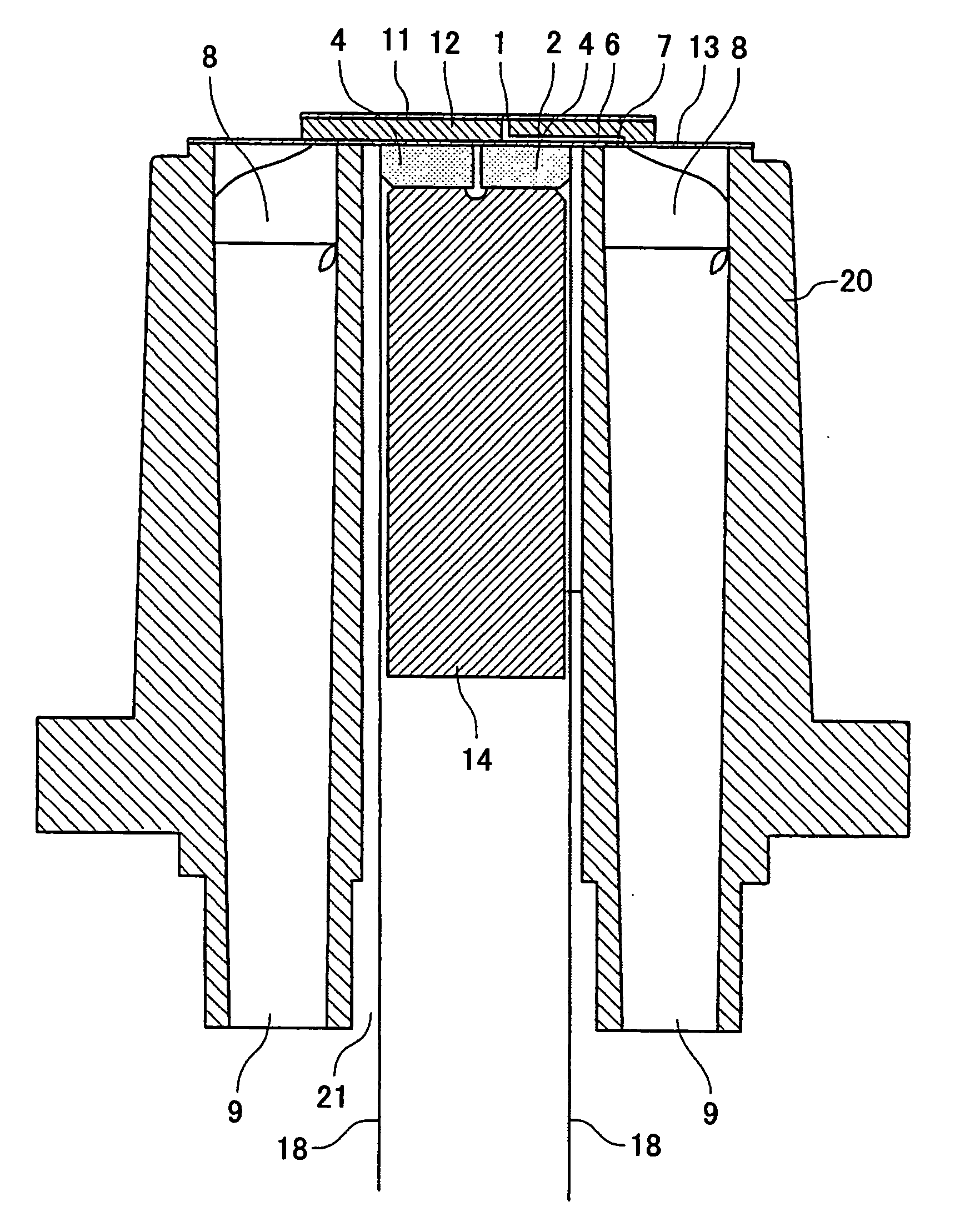
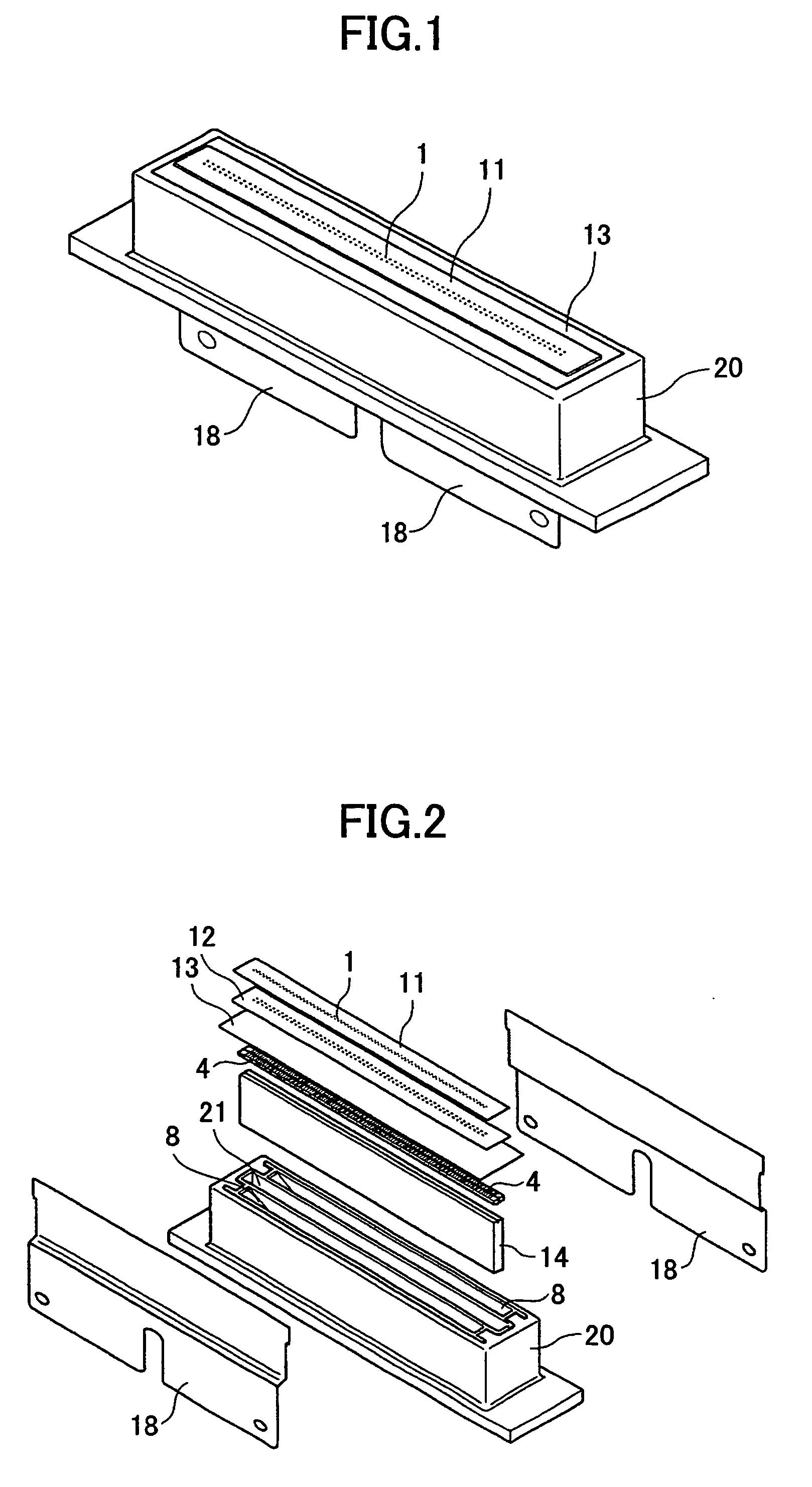
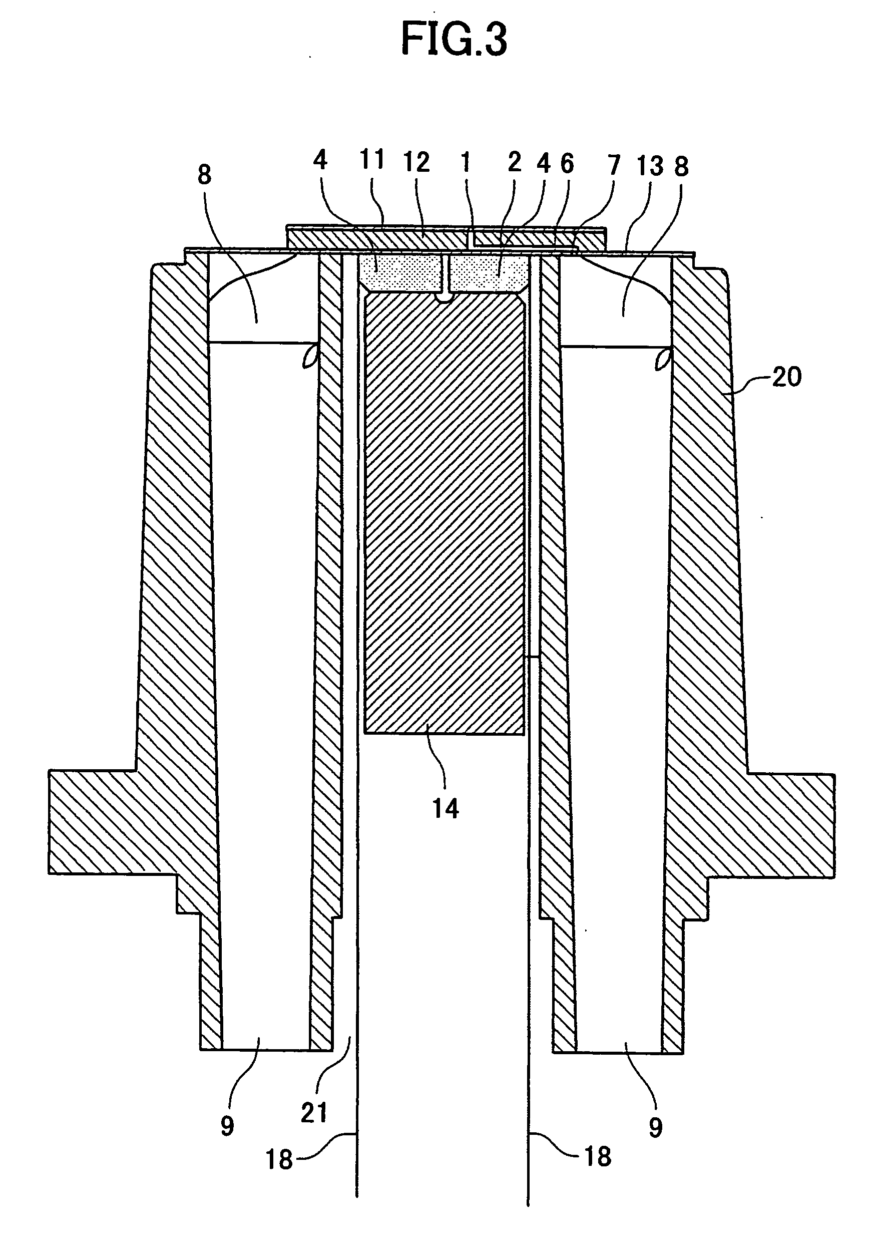
[0030] A description of the present invention and details of drawbacks of the related art are now given, with reference to FIG. 1 through FIG. 7, including embodiments of the present invention. First, a liquid discharge head of the present invention is discussed with reference to FIG. 1 through FIG. 3. FIG. 1 is a perspective view of the exterior of the liquid drop discharge head. FIG. 2 is an exploded perspective view of the liquid drop discharge head. FIG. 3 is a cross-sectional view of the liquid drop discharge head.

[0031] The liquid drop discharge head has a nozzle 1 for discharging a liquid drop, a pressure room 2 connected to the nozzle 1, a vibration plate 3 (not shown) forming a part of a side surface of the pressure room 2, and a piezoelectric element 4 as actuator means such as pressure generation means or driving means for pressing the liquid in the pressure room 2 via the vibration plate 3. The liquid drop discharge head also has a common liquid room 8 and a supply openi...

second embodiment

[0043] In the second embodiment, a ceramic whose main ingredient is potassium niobate (KNbO3) that is a material having a perovskite type crystal structure not including lead is used as a piezoelectric material (piezoelectric ceramic) of the piezoelectric element 4.

[0044] The ceramic whose main ingredient is potassium niobate has an electrical-mechanical coupling coefficient of 0.5, similar with PZT's electrical-mechanical coupling coefficient. Furthermore, the ceramic whose main ingredient is potassium niobate has the perovskite type crystal structure and therefore it is possible to obtain a good piezoelectric property such as small crystal anisotropy. Since the Curie temperature of the ceramic whose main ingredient is potassium niobate is high (approximately 435° C.), it is possible to mount the FPC by soldering as well as the PZT.

[0045] Thus, in the second embodiment as well as the first embodiment, since lead is not included at all in the piezoelectric element as the actuator m...

third embodiment

[0047] In the third embodiment, a ceramic whose main ingredient is bismuth sodium titanate ((Bi0.5Na0.5)TiO3) that is a material having a perovskite type crystal structure not including lead is used as a piezoelectric material (piezoelectric ceramic) of the piezoelectric element 4.

[0048] Since a sintering temperature of the ceramic whose main ingredient is bismuth sodium titanate is equal to or less than 1200° C., it is possible to reduce the amount of the palladium, an extremely expensive metal, in the internal layer electrode, so that it is possible to manufacture the piezoelectric element 4 at low cost.

[0049] Thus, in the third embodiment as well as the first and second embodiments, since lead is not included at all in the piezoelectric element as the actuator means in the liquid drop discharge head, it is possible to make the environmental pollution risk low and make the dismantling cost low.

[0050] Next, the fourth embodiment of the liquid drop discharge head of the present in...


PUM


Abstract

A liquid drop discharge head includes a nozzle configured to discharge a liquid drop by using a piezoelectric element. Lead ingredients are not included in the piezoelectric element.

Description

TECHNICAL FIELD [0001] The present invention relates to liquid drop discharge heads, liquid drop discharge devices, and image forming devices. BACKGROUND ART [0002] An ink jet recording device having a liquid drop discharge device including a liquid drop discharge head is known as an image forming device such as a printer, facsimile, copier, and multifunction device of the printer, facsimile, and copier. [0003] In the ink jet recording device, a liquid drop of a recording liquid is jetted from a recording head to a recorded medium such as a paper, an OHP (Overhead Projector) film, a recording medium or a recording paper, so that image forming such as recording, printing, or copying can be performed. It is possible to record a high precision image with high speed by the ink jet recording device on the recording medium. In addition, running cost is cheap and noise is small in the ink jet recording device. Furthermore, it is easy to record a color image by using a lot of kinds of color...

Claims


Application Information

Patent Timeline
IPC IPC(8): B41J2/045B41J2/055B41J2/14H01L41/09
CPCB41J2/14201B41J2202/03B41J2/14274B41J2/045
Inventor YAMAGUCHI, KIYOSHISASAKI, TAKAFUMI
Owner RICOH KK
Learn More